That is one way of putting it. 😆If that was DiyLC, then I agree is is not perfect[...]
I doubt will being so illogical and so different from CAD. Though it helped to think of it as a toy for a hobby rather than a serious drafting tool for work. 🤔[...]but once you get the hang of it[...]
I have not come across this, however, reminds me I forgot to finish the layout book. Being unaware didn't take advantage of this opportunity.[...]turning the valve bases so they are optimised for heat dissipation[...]
I saw that though wasn't sure be an advantage. Now it is very obvious as then allows for installing a ECL86 with its one Noval base. Here is the pinout so on the same page.DIYLC comes with octal and noval tubes bases and you can label the pins. Just lable the pins for the tubes that you are using (for instance a, k, g, h, h, a1, k1, g1 for a dual triode) then use that to get the placement correct.
Attachments
Mine on the computer has both at 310. I looked at yours and only saw 325V.You have two schematics. In one the output tubes' power supply (V1) is 310V, in the other 325V.
I know this, look at one of my early posts where concerned about the L1's 325 supply voltage, knowing the EL84 is rated to 300V. Also, just the other day said when I increased the B+ I would check the plate dissipation. Why would I do this if didn't know this? 🤔 Neurotypicals are interesting is all I am observing. Maybe this is a reminder? 🤔That is the reason you get bigger dissipation on the one with V1 at 325V.
I recall changing both B+ and B++ voltages for distortion, see no reason to run higher if going to be no benefit, worse, if going to damage tubes. As I understand, the ECC81 and ECC83 should not have more than 250V; I forget the EF86 though seems in this schematic to be the least affected by voltage.
Edit. Add that I am amused it is plate dissipation that is the concern, I thought really hear it regarding having two supply voltages.
I did not read the whole thread, so I apologize if this is redundant.
"Selecting capacitors " It is very important that some of these capacitors are of a certain type. Some of the capacitors the OP asked about, like the input low pass filter and the filters around the stages, should almost certainly be ceramic "high Q" capacitors. Their high frequency characteristics are vital to the correct performance of the circuit.
People talk about the nonlinearity of the capacitors etc but in these applications that is not the important parameter. If anyone tries to replace some of these capacitors with some kind of "audiophile" capacitors, there will likely be some noticeable nonlinearities. Cyril Bateman (and others) published an article about capacitor choices for circuits many years ago.
The schematic shows a typical "ultralinear" amplifier, quite nice.
I sometimes also use multiple power supplies when simulating circuits, it allows changing voltage in a sections of the schematic and leaving the rest intact.Edit. Add that I am amused it is plate dissipation that is the concern, I thought really hear it regarding having two supply voltages.
The plate power dissipation was the concern 🙂
Okay.I sometimes also use multiple power supplies when simulating circuits, it allows changing voltage in a sections of the schematic and leaving the rest intact.
This is where I got the idea. To be clear, don't plan to use this, just pointing out a source which happens to do it in the final product. 🙂
I do appreciate the concern, thank you! 😀The plate power dissipation was the concern 🙂
It is not redundant and appreciate the help, thank you. 😀I did not read the whole thread, so I apologize if this is redundant.
Firstly, are you referring to the coupling caps, for example, C7 and C8?Some of the capacitors the OP asked about, like the input low pass filter and the filters around the stages, should almost certainly be ceramic "high Q" capacitors.
Secondly, what are ""high Q" capacitors"?
I take it you mean using audio grade caps would be detrimental to the sound?If anyone tries to replace some of these capacitors with some kind of "audiophile" capacitors, there will likely be some noticeable nonlinearities.
These? https://linearaudio.nl/cyril-batemans-capacitor-sound-articlesCyril Bateman (and others) published an article about capacitor choices for circuits many years ago.
Which one, this one?The schematic shows a typical "ultralinear" amplifier, quite nice.
Friend is late, trying the mobile version, finding doesn’t allow quotes.
Richard (@OldHector ), the book only gives a few sentences about tube heat with the only mention of orientation being heater pins turned so closest to chassis edge. Does this also benefit tube heat rejection?
Richard (@OldHector ), the book only gives a few sentences about tube heat with the only mention of orientation being heater pins turned so closest to chassis edge. Does this also benefit tube heat rejection?
High "Q" capacitors are high resonance, low inductance capacitors. Old tube equipment is filled with them. They are used for their high frequency characteristics. There is nothing to be gained by replacing them with "audio grade" capacitors - and possibly something to be lost; stability could be affected.
The coupling capacitors could possibly be replaced by "audio grade" capacitors. I wouldn't alter their value though. The low frequency pole is required for stability. Unlike modern amplifiers, transformer coupled amplifiers have both high frequency and low frequency poles to deal with in the feedback loop.
The coupling capacitors could possibly be replaced by "audio grade" capacitors. I wouldn't alter their value though. The low frequency pole is required for stability. Unlike modern amplifiers, transformer coupled amplifiers have both high frequency and low frequency poles to deal with in the feedback loop.
Hi Adriel, I think you are missing the point of DiyLC. It is to determine the layout, so use a 9 pin tube base on the drawing, label the pins, and work out how the grid will be connected from the tagboard, for example. You can route the heater wiring, and look at the best orientation of the bigger components. Tubes radiate more in certain directions, so once you have optimised the heater wiring, you can look st the plated on your tubes and have them pointing away from heat sensitive components.
This and a forum search are not helping. @Merlinb 's book regarding pre amplifier design, page 76-86, sections 2.2.10 though 2.2.14, supplies a wealth of information on: Air, Mica, Ceramic, Film, and Aluminium Electrolytics, no mention of Q as a capacitor or a value; don't recall seeing them in Mouser's catalogue either. 🤔High "Q" capacitors are high resonance, low inductance capacitors. Old tube equipment is filled with them. They are used for their high frequency characteristics. There is nothing to be gained by replacing them with "audio grade" capacitors - and possibly something to be lost; stability could be affected.
I am a tactile learner, so how about use this schematic you like?
So we have:
Input filter (not shown on the schematic) - Ceramic cogs.
C1, C4, C9, and C10, which are low voltage going to earth - Ceramic cogs or film?
C3, in the audio path - audio quality capacitor, electrolytic or film? Low voltage, correct?
C2, C7, and C8, high voltage in the audio path - audio quality capacitor, electrolytic or film?
Thank you, will do. 🙂The coupling capacitors could possibly be replaced by "audio grade" capacitors. I wouldn't alter their value though. The low frequency pole is required for stability. Unlike modern amplifiers, transformer coupled amplifiers have both high frequency and low frequency poles to deal with in the feedback loop.
I do in fact understand the purpose of DIYLC, rather, the interface is terribly lacking when compared to the professional drafting programs I already know. However, this is not required and require research to find all the dimensions, build components, all before laying out. Another way to say this is it is SketchUp, which is only good for sketching, versus ArchiCAD that is a true BIM program and draft assemblies showing all components, rather than just a thick plane. Maybe not the analogy, maybe substitute AutoCAD which is also professional, though takes extra steps to create a 3D model (few of us are left who know how to, replaced by the lackluster Revit (sp?)). ArchiCAD will always be the best structure's drafting and modeling program, the first of BIM.Hi Adriel, I think you are missing the point of DiyLC. It is to determine the layout, so use a 9 pin tube base on the drawing, label the pins, and work out how the grid will be connected from the tagboard, for example.
As for tagboard, you prefer over running wire?
In this example, the warmest be facing pins six and nine, with the coolest facing pin one or facing three and eight, correct?Tubes radiate more in certain directions, so once you have optimised the heater wiring, you can look st the plated on your tubes and have them pointing away from heat sensitive components.
"Q" is old school talk. I'm talking about ceramic disc capacitors like this. https://www.mouser.com/c/passive-co...-capacitors/ceramic-disc-capacitors/?m=Vishay I have a million of them in stock.
I'm a mack from way back. In the day anyone would have known what a "high Q" capacitor was.
I'm a mack from way back. In the day anyone would have known what a "high Q" capacitor was.
I thought it was some form of ceramic or a specification. Thank you for clarifying. 🙂"Q" is old school talk. I'm talking about ceramic disc capacitors like this. https://www.mouser.com/c/passive-co...-capacitors/ceramic-disc-capacitors/?m=Vishay I have a million of them in stock.
Interesting part of my post was clipped off, try again:
So we have:
Input filter (not shown on the schematic) - Ceramic cogs.
C1, C4, C9, and C10, which are low voltage going to earth - Ceramic cogs or film?
C3, in the audio path - audio quality capacitor, electrolytic or film? Low voltage, correct?
C2, C7, and C8, high voltage in the audio path - audio quality capacitor, electrolytic or film?
@kodabmx , turns out can export a .png image.

Richard (@OldHector ), is this more along what you are meaning?
The other flaw I forgot to say is don't layer everything the same, so some things are not visible, like the jumpers.
Richard (@OldHector ), is this more along what you are meaning?
The other flaw I forgot to say is don't layer everything the same, so some things are not visible, like the jumpers.
Adriel, come on already😵
This thread has become epitome of "The" antithetical build..
Me thinks we need to start a 'Gofundme' page for your soldering iron
Jim
This thread has become epitome of "The" antithetical build..
Me thinks we need to start a 'Gofundme' page for your soldering iron
Jim
Well, if you had not bailed on helping build the L1... 😛Adriel, come on already😵
😆This thread has become epitome of "The" antithetical build..
I am not sure if being silly or serious...Me thinks we need to start a 'Gofundme' page for your soldering iron
That's your interpretation of direction, is that only one should be considered?Well, if you had not bailed on helping build the L1... 😛
IMO, this forum is for growth in the hobby. Since your here, then qualifies? Perhaps need to specify your desire of brain trust here?
Either:
1. To synthesize
2. To fabricate
There is synergistic balance between them...
Bothis?I am not sure if being silly or serious...
This is some layouts I did for my last project, the original Dissident Audio Baby Huey.Richard (@OldHector ), is this more along what you are meaning?
It was meant to be a compact build, and that was the main challenge. The transformers could not be mounted on the top plate and had to drop through, so a lot of my planned space disappeared.
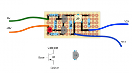
The CCS for the driver ...
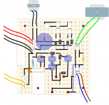
The power supply, with seperate supply for the negative rail ...
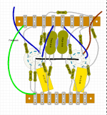
Packing the the components for one channel of the amplifier ...
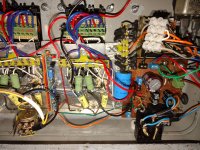
As built ...
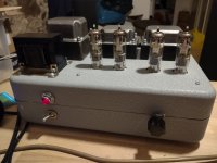
There were a lot of constraints that were not planned at the start, so it took a lot of iterations and a few months to complete. That is why I recommend getting started with a PCB build, like the Tubelab SPP, by reasonable parts, and cut your teeth.
I am not sure what you are asking. Mind clarifying?That's your interpretation of direction, is that only one should be considered?
My guess be not understanding my teasing you. If I had the help seemed promised, would have built the L1 clone, never needing to question the design. See, instead of them simply answering what the values are, mentioned about the feedback loop and one thing led to another. The more I learned, the more I questioned and looked into other options. Now the thread is a few pages long.
Which it has been, even social skills (which I severely lack because of missing it due to the Autism).IMO, this forum is for growth in the hobby.
What is your purpose in stating this?Either:
1. To synthesize
2. To fabricate
There is synergistic balance between them...
Well, my hang up is spending what money I have on a design that disappoint. Then there was the concern going at it on my own (why initially chose the L1 clone) though now know I can build anything, just have to follow the schematic, be patient, use perf board, and in keeping with the last point, remember it will need troubleshooting and adjusting to get sound. If someone wants to help, I am open to it.Both
By the way, Go Fund Me charges the highest percentage, for you all's information.
I am sorry, rarely understand hints. So is the layout shown satisfactory?This is some layouts I did for my last project, the original Dissident Audio Baby Huey.
Why?The transformers could not be mounted on the top plate and had to drop through, so a lot of my planned space disappeared.
I was looking for a rail and couldn't find one. Maybe I am totally missing it...The power supply, with seperate supply for the negative rail ...
Neat, thank you for sharing. 🙂As built ...
I don't see doing point to point as a hill that can't be surmounted. Well then, I looked with no real success (no reviews) and not finding an ECL82 or ECL86 SE kit, can you recommend one? If not, then PCB isn't an option, as doesn't exist. Might as well keep it super simple and something enjoyable.There were a lot of constraints that were not planned at the start, so it took a lot of iterations and a few months to complete. That is why I recommend getting started with a PCB build, like the Tubelab SPP, by reasonable parts, and cut your teeth.
- Home
- Amplifiers
- Tubes / Valves
- Selecting Capacitor(s) and Resistor(s)
