See, I am at least leery of trusting, if not un-trusting, of humans because have been hurt so many times (including child abuse)
Not the first time you've brought personal issues into this discussion..
May be mistaken, but I dont think this is proper place to vent those issues, especially if used to bludgeon members...
Not a person alive this world hasn't had to deal w/ issues- part of growing up,, so get your big boy pants on and stop complaining
Don't care what your having for breakfast- this isn't Facebook
Since monetary limits are your primary concern, it's no brainer to go with existing design that's real world proven over and over, like others experience w/ tubelab's SPP!
Why? cuz it takes synthetic theory and adds refinement of real world testing... let that sink in before you post to the contrary... if missed...
Read this again
Bottom line,
There is a balance between theory and reality,, Adriel, stop getting lost in the middle
I- We- are only trying to help you achieve your objective, but the goal posts are transitory... again.. and again.. and again
Pretty sure OP will continue to propagate, when is enough enough?
And stop saying you don't understand as an excuse to prolong
Last edited:

Its not that exactly. One manufacturer may not make every type of part. Some parts for point to point wiring may only be made in China these days. Don't know for sure. So let's not jump to conclusions.Interesting the book shows a style no longer available...
Part of the problem when searching for parts is to figure out the most common name for an item of interest. Here is a search I did to look for certain types of point to point wiring solder terminals: https://www.google.com/search?q=FR4...1C1CHBF_enUS771US771&sourceid=chrome&ie=UTF-8 As can be seen there are various types that may be available if we know how to figure out the most effective words or terms to search for particular items.
Sometimes that searching skill may be referred to as "Googlefoo."
Last edited:
instead of questioning values of resistors and other parts, why not understand the whole design instead...I am of the persuasion it is best to understand any amplifier you are building, so if understood how your response is related to the question you responded to, then would have value to me, hopefully others understand and find value.
Thank you for letting me know. 😀 Only downside is the limited values in flame proofs (I am paranoid due to family and personal experience (wildfire, thankfully skipped over our end of the street)), examples, no 47Ω, only 47,5Ω, though a better example be 820KΩ, nothing remotely close, closest is 825KΩ.
Though an indirect suggestion, fell in love with this design much to the liking of many (I am being sarcastic): http://www.r-type.org/articles/art-008.htm.
get yourself a copy of Morgan Jones tubes about valves or Merlin Blencowe's books...
@oemcar , why the shear nastiness, is it because I am Autistic? If so, not the first nor the last. Only reason I can think of, never once been mean or rude to anyone on this forum.
Agreed, there is risk doing something on your own, however, there is also greater reward. Worse case, make some tweaks. Thanks to @jcalvarez it has been shown the design is buildable and should provide more than satisfactory results. Even thanks to him and @kodabmx have less expensive methods of testing the built amplifier; knowing what I know now not sure be best to deviate without this.
I know others are, full of knowledge and experience, why I ask questions. Is that not the point of a forum?
Hope tomorrow is a better day for you. 🙂
Do you realize how extremely rude this is? I was trying to explain my bias in hopes in case misunderstood would know where coming from. Unlike some folks, I go out of my way to be nice.Not the first time you've brought personal issues into this discussion..
May be mistaken, but I dont think this is proper place to vent those issues, especially if used to bludgeon members...
I don't give a flying flip what you think.In fact, don't care what anyone thinks of me, I am an eccentric and live my life as see fit so long as keeping with being kind and considerate. I said it to let @TonyTecson wasn't ignoring him.Don't care what your having for breakfast- this isn't Facebook
Where did I say it was a primary regarding the EL? Post number, please.Since monetary limits are your primary concern, it's no brainer to go with existing design that's real world proven over and over, like others experience w/ tubelab's SPP!
Why? cuz it takes synthetic theory and adds refinement of real world testing... let that sink in before you post to the contrary... if missed...
Read this again
Agreed, there is risk doing something on your own, however, there is also greater reward. Worse case, make some tweaks. Thanks to @jcalvarez it has been shown the design is buildable and should provide more than satisfactory results. Even thanks to him and @kodabmx have less expensive methods of testing the built amplifier; knowing what I know now not sure be best to deviate without this.
Theory and understanding is necessary to build a nicer amplifier. Some folks maybe fine with knowing nothing about amplifiers and assembling a kit, that isn't me. If that is someone's bag, fine, each to their own. Suggest adopt that attitude. 🙂Bottom line,
There is a balance between theory and reality,, Adriel, stop getting lost in the middle
You are?I- We- are only trying to help you achieve your objective[...]
I know others are, full of knowledge and experience, why I ask questions. Is that not the point of a forum?
Interesting how getting angry with me because you backed out of your promise to help with the L1 clone. I have settled on a a design, suggest instead of making a fool of yourself, to read through and see how we have been sussing out a design.[...]but the goal posts are transitory... again.. and again.. and again
Almost there, got the revised layout done not that long ago, welcome to critique it and get this moving along. Once the layout is sorted, then order parts and move to the next steps.Pretty sure OP will continue to propagate, when is enough enough?
And stop saying you don't understand as an excuse to prolong
Hope tomorrow is a better day for you. 🙂
Good point. Assumed because neither of us could find it that does not exist.Its not that exactly. One manufacturer may not make every type of part. Some parts for point to point wiring may only be made in China these days. Don't know for sure. So let's not jump to conclusions.
How am I to know another name is "FR4"? I thought that was the suppliers part number. Thank you for correcting that, appreciated! 😀Part of the problem when searching for parts is to figure out the most common name for an item of interest. Here is a search I did to look for certain types of point to point wiring solder terminals: https://www.google.com/search?q=FR4...1C1CHBF_enUS771US771&sourceid=chrome&ie=UTF-8 As can be seen there are various types that may be available if we know how to figure out the most effective words or terms to search for particular items.
Speaking of FR4s, it got the amplifier even more compact. Then taking @OldHector 's suggestion to use axial caps, down to 3"/75cmx3"/75cm Thank you both! 😀
Last edited:
Exactly!instead of questioning values of resistors and other parts, why not understand the whole design instead...
get yourself a copy of Morgan Jones tubes about valves or Merlin Blencowe's books...
I have read both of Morgan's books (where the black and white pictures came from) and working on Merlin's pre amplifier book. There is so much to digest, might miss a thing or two. So then what page is this quiescent discussed, please? 🙂
By the way, one of Merlin's tidbits made a huge improvement to the amplifier design, about halved distortion IIRC (can get the actual numbers some other time if so desired).
Hi Adriel, I think there is a bit of frustration seeping into this discussion. FYI I 👍 oemcar's response to you because of the comment about Facebook - I was starting to think myself that this thread has morphed into something else than it's original premise, which was to seek advice prior to building an amplifier; it is drifting with superflous detail.
I asked you if you could take stock and restate your primary goal. A thread should cover a 'topic' and prompt discussion, and ultimately be resolved. There can be no resolution if we are unsure what the topic is we are discussing.
Your DiyLC layout above looks neat. I do think you should label the pins on the valve bases so you know which pin is what, that makes it more meaningful to other people when they look at it. If you do not care about that, and you know what you did in 6 months time, then I suppose it makes no difference. You could also use the 'both' option for naming components so that the component number and value are both displayed. That also makes it easier to sanity check.
I was certain DiyLC has tag board, so I was quite surprised that is does not exist! There are other options, for example two tag strips with the same number of tags in parallel, or get creative with the different board options and spacing of solder pads. I would probably use the Eyelet Board, and fix the spacing to be the same for adjacent tags. As long as the basic spacing is aligned with real tag board then you can focus on the layout without any worries.
I spent the day on a layout yesterday, so I can imagine how many hours of work you have in your layout. It is fiddly with bendy leads.
I was a little disappointed that you felt my previous reply to you was a little 'nasty'. It absolutely was not, and I think perhaps you should consciously try not to be defensive in your replies to people here. We are all trying to contribute, and most of the people you have replying to you are experts giving there time and advice freely, it is just that written discussion can be tricky if you see a negative interpretation.
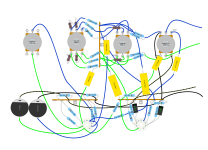
Apropos nothing, here is the layout I am working on. It is a Baxendall tone stack with volume and balance controls for an old stereo amp I am trying to breath life back into, but us starting to feel like a project too far. I have spread out the parts a bit to make it easier to do the layout. As mentioned above those bendy leads are a real pain in the derrière!
Please stay positive, but also please bear in mind the audience does not have unlimited patience, especially if there is no clear issue to be solved.
Cheers, Richard
I asked you if you could take stock and restate your primary goal. A thread should cover a 'topic' and prompt discussion, and ultimately be resolved. There can be no resolution if we are unsure what the topic is we are discussing.
Your DiyLC layout above looks neat. I do think you should label the pins on the valve bases so you know which pin is what, that makes it more meaningful to other people when they look at it. If you do not care about that, and you know what you did in 6 months time, then I suppose it makes no difference. You could also use the 'both' option for naming components so that the component number and value are both displayed. That also makes it easier to sanity check.
I was certain DiyLC has tag board, so I was quite surprised that is does not exist! There are other options, for example two tag strips with the same number of tags in parallel, or get creative with the different board options and spacing of solder pads. I would probably use the Eyelet Board, and fix the spacing to be the same for adjacent tags. As long as the basic spacing is aligned with real tag board then you can focus on the layout without any worries.
I spent the day on a layout yesterday, so I can imagine how many hours of work you have in your layout. It is fiddly with bendy leads.
I was a little disappointed that you felt my previous reply to you was a little 'nasty'. It absolutely was not, and I think perhaps you should consciously try not to be defensive in your replies to people here. We are all trying to contribute, and most of the people you have replying to you are experts giving there time and advice freely, it is just that written discussion can be tricky if you see a negative interpretation.
Apropos nothing, here is the layout I am working on. It is a Baxendall tone stack with volume and balance controls for an old stereo amp I am trying to breath life back into, but us starting to feel like a project too far. I have spread out the parts a bit to make it easier to do the layout. As mentioned above those bendy leads are a real pain in the derrière!
Please stay positive, but also please bear in mind the audience does not have unlimited patience, especially if there is no clear issue to be solved.
Cheers, Richard
Attachments
Okay, certainly not my intent. 🙂I think there is a bit of frustration seeping into this discussion. FYI
I have done that all my life even when try not to, drove Dad crazy. Maybe one day will be able to get right to the point, trick is knowing how much information and not allowing my being alone not creep into my online conversations. Oops.oemcar's response to you because of the comment about Facebook - I was starting to think myself that this thread has morphed into something else than it's original premise, which was to seek advice prior to building an amplifier; it is drifting with superflous detail.
It didn't cross my mind we are the only ones using DiyLC or that wouldn't be obvious it was a layout sketch, good to know though maybe too late. Not sure how to resolve, other than start a new thread for each topic.I asked you if you could take stock and restate your primary goal. A thread should cover a 'topic' and prompt discussion, and ultimately be resolved. There can be no resolution if we are unsure what the topic is we are discussing.
Thank you. 🙂Your DiyLC layout above looks neat.
Okay, will see if can darken the text. Also need to do a .gif again, in a hurry last night.I do think you should label the pins on the valve bases so you know which pin is what, that makes it more meaningful to other people when they look at it. If you do not care about that, and you know what you did in 6 months time, then I suppose it makes no difference. You could also use the 'both' option for naming components so that the component number and value are both displayed. That also makes it easier to sanity check.
Appreciate the compliment.I spent the day on a layout yesterday, so I can imagine how many hours of work you have in your layout. It is fiddly with bendy leads.
A lot of it is copy, paste, and sometimes adjust. 😉
Came across as provide the goal or not helping you; would have helped including a critique of the provided layout as Mark did. Took me by surprise asking again and especially making a demand, past conversations have been present. Maybe need to instead ask if it is the intent, when feeling absolutely terrible hard to remember all these little techniques taught to me by a professional. I will try better in the future. 🙂I was a little disappointed that you felt my previous reply to you was a little 'nasty'. It absolutely was not, and I think perhaps you should consciously try not to be defensive in your replies to people here. We are all trying to contribute, and most of the people you have replying to you are experts giving there time and advice freely, it is just that written discussion can be tricky if you see a negative interpretation.
Nifty. 🙂Apropos nothing, here is the layout I am working on. It is a Baxendall tone stack with volume and balance controls for an old stereo amp I am trying to breath life back into, but us starting to feel like a project too far. I have spread out the parts a bit to make it easier to do the layout. As mentioned above those bendy leads are a real pain in the derrière!
You know you can copy and paste colors to make bent leads on condensers and resistors? I did on mine for clarity, though seems yours was only for your eyes.
What may be plain as day might not to be others, the trouble is knowing when that is going to happen. Also, a person can have the decency, like you did, to let me know not obvious.Please stay positive, but also please bear in mind the audience does not have unlimited patience, especially if there is no clear issue to be solved.
the way you ask questions indicate you did not see anything there..
Thank you! 😀By the way Adriel, just checking to make sure you are aware that tag strips are typically mounted on standoffs, not free floating?
I was not aware until looking at the parts , thought like tag strips that mounted to the chassis. I have gotten myself confused on the mounting, think best leave alone, position is close for any of the options, more importantly parts are selected that fit and where fit best (starting with heat output), while avoiding the heater wiring.
Cheap as chips option.
Hit me the *SN7 is a dual triode like the ECC83, quick look and sure enough can be subbed in, no changes, and adapters are available. Took me all of five minutes to swap the tubes, so no true delay. 😛 No need to reply, just putting here in case anyone is curious. Fun rolling tubes in LTSpice, though I am done.
Here is the ECC83.

Then the *SN7, don't see this as so detrimental that makes it not an option. Bet a *SL7 bump it back up, though not as inexpensive.

Hit me the *SN7 is a dual triode like the ECC83, quick look and sure enough can be subbed in, no changes, and adapters are available. Took me all of five minutes to swap the tubes, so no true delay. 😛 No need to reply, just putting here in case anyone is curious. Fun rolling tubes in LTSpice, though I am done.
Here is the ECC83.
Then the *SN7, don't see this as so detrimental that makes it not an option. Bet a *SL7 bump it back up, though not as inexpensive.
Last edited:
Ah, yes, of course, signal jumping over, oops; what I get for copying and pasting. Well then, only bend one leg rather then both (they are legs and not leads), the original leg pointing down becomes the one soldered to the tang and the other bent out to connect to the resistor. Might need to create a little block for the caps to rest on so the resistor is not drooping onto the tang.Looks like C7, C8 may still be shorted in the wiring diagram?
If all there is, think did well.
Please annotate the tube pins (when you choose the socket you can choose the tube type so you don't need to do this yourself), add the values to the components (use the 'both' option for name) and post the circuit you are planning to build.Here is the latest iteration, feedback would be appreciated.
The 6SN7 is very different from an ECC83. Much more power, way less gain. Very popular to drive high(er) powered output tubes like 6L6, EL34, KT88 etc.Cheap as chips option.
Hit me the *SN7 is a dual triode like the ECC83, quick look and sure enough can be subbed in, no changes, and adapters are available. Took me all of five minutes to swap the tubes, so no true delay. 😛 No need to reply, just putting here in case anyone is curious. Fun rolling tubes in LTSpice, though I am done.
Here is the ECC83.
View attachment 1153000
Then the *SN7, don't see this as so detrimental that makes it not an option. Bet a *SL7 bump it back up, though not as inexpensive.
View attachment 1153001
The 6SL7 can replace an ECC83, yes, just taking into account that the sockets are completely different.
There are very reasonably priced Soviet equivalents (6N8S/6N9S).
I hope it was OK to reply 🙂😛 No need to reply
Yes, I clearly forgot to change the color of the sockets.Please annotate the tube pins (when you choose the socket you can choose the tube type so you don't need to do this yourself), add the values to the components (use the 'both' option for name) and post the circuit you are planning to build.
I removed the banding in hopes make the text more visible, also the ones I selected don't have banding.
Thank you for the correction. 😀The 6SN7 is very different from an ECC83. Much more power, way less gain. Very popular to drive high(er) powered output tubes like 6L6, EL34, KT88 etc.
The 6SL7 can replace an ECC83, yes, just taking into account that the sockets are completely different.
Wow! Look at the difference to the *SN7, also slightly better then the ECC83.
As for the Noval to octal, there are adapters. This would keep the chassis small.
Ha. More than okay. 🙂 Some caring folks are trying to keep me on the path to a final product and letting them know it's okay. See, three or for post and das ist alles.I hope it was OK to reply 🙂
- Home
- Amplifiers
- Tubes / Valves
- Selecting Capacitor(s) and Resistor(s)