I have only seen one guy on e-Bay selling PCL86 SE board. But no reviews.
Kits are mostly build for current production tubes like EL84, 6L6 etc. ECL/PCL and other television tubes are not produced anymore.
https://www.ebay.co.uk/itm/22505481...eyvgl_xSMK&var=&widget_ver=artemis&media=COPY
Kits are mostly build for current production tubes like EL84, 6L6 etc. ECL/PCL and other television tubes are not produced anymore.
https://www.ebay.co.uk/itm/22505481...eyvgl_xSMK&var=&widget_ver=artemis&media=COPY

I found a few reviews in the seller's feedback. For $9USD plus $6 shipping, doesn't seem too much a loss. The components can be stripped and used for something else if absolutely terrible.I have only seen one guy on e-Bay selling PCL86 SE board. But no reviews.
Ah, good to know, thank you. 🙂Kits are mostly build for current production tubes like EL84, 6L6 etc. ECL/PCL and other television tubes are not produced anymore.
By the way, the ECL86 was used in period hifi equipment. http://www.r-type.org/exhib/aaa0034.htm
Thank you. 😀 Only downside is the estimated shipping time is a month, will sleep on it (try to always do this, impulse purchasing is not wise for the financially disenfranchised).
Sidenote. I couldn't wait for the Mouser order (not going to buy two caps alone) so hooked up the Jensen speakers, TT, and put on a LP. Wow, amazing what great equipment can do with poor quality speakers! That little class D is defiantly going in the donate bin, don't need stuff not going to use sitting around. Just think what it will sound like with fantastic tube amplifier instead of SS! 🤤
The plans I shared were just meant to be examples of the steps in going down the point-to-point wiring route. Many people here are very experienced and can get on with it without having to plan so much; others are happy with a dog's dinner, but that is not for me because I want someone else to be confident with what I produce.I don't see doing point to point as a hill that can't be surmounted. Well then, I looked with no real success (no reviews) and not finding an ECL82 or ECL86 SE kit, can you recommend one? If not, then PCB isn't an option, as doesn't exist. Might as well keep it super simple and something enjoyable.
Please do not go down another rabbit hole and start to look at an ECL86 SE PCB (the Baby Huey is PP ECL86 by the way)! It is just for illustration to nudge you along 🙂
Will I get the help offered regarding layout review? I ask this as see no point fighting with the program if no one will review the layout, rather do it with tangible objects. 🤔The plans I shared were just meant to be examples of the steps in going down the point-to-point wiring route.
I do want to plan, I can't stand mess. Plus, means easier to diagnose and repair, including those in the future.[...] others are happy with a dog's dinner, but that is not for me because I want someone else to be confident with what I produce.
Well, are you taking back the advice given twice and build something off PCB first?Please do not go down another rabbit hole and start to look at an ECL86 SE PCB (the Baby Huey is PP ECL86 by the way)!
I kind of have... In my trying to model a few, for more practice, and pick one. Not today, just got home and catching up.
Thank you! 😀It is just for illustration to nudge you along 🙂
How this nudge me along?
I realized the other day I was being silly and/or thick, got to it, and so, banged out a rough draft. Here it is, can someone please check my connections? How about the layout?
One thing I assumed is the cap legs and valve socket tabs can be terminals, rather then follow the schematic where has a lead and then a connection; logic seems to suggest doesn't matter.
I spent half of the time laying out the heater wiring, wires cross the supply and signal wires at 90 degrees, on a separate ground, and the ground terminals are next to the resistors, rather then the supply wires to hopefully reduce hum. Put what I could in the doghouse as figured the metal casings of the caps protect them and keep the dirty stuff together (my understanding is electrolytic caps generate some EMF); could plate the caps mounting surface so the heater wires already running underneath are shielded if still an issue with hum.
In the end, so glad I did this, made a lot of changes, especially in the mounting and arrangement of caps and resistors; much neater. If did it with actual parts, end up buying tag strips instead of terminal strips, for example. Additionally, adding to the ease of assembly is labeled everything the same as the schematic, mostly for ease and partly as looks like can generate a BOM. See, now the diagram can be used to identify resistor sizes using the banding code.
By the way, I find these caps and resistors all laid in rows knock out gorgeous then scattered on a PCB, over all it is just beautiful.
My only disappointment is not knowing for sure using the right kind of caps, might be over doing it with film.
Thank you Richard (@OldHector )! 😀
Just realized forgot to delete my layout lines... 😆
Hi Adriel, Looking back at my own layouts, I realised I did two versions of the drawing, and used one just for the heater wiring. The heater wiring is done before anything else and I don't think it should be using the valuable tags on your tag strips - it can be joined to the power transformer using connection blocks.
DiyLC does have a twisted pair if you want to make the heating wiring looked authentic. Putting the heater wiring on a separate view declutters the main layout diagram.
It looks to me like you have got components going across the same tags of the tag strip - i.e. they are shorted by the tags. For example R7?
Once you start to look at a layout like this, the lead length and shape of components becomes more important. With point-to-point axial capacitors are a lot easier to work with than radial because they have longer leads at both ends of the body of the component. IMO you do not need all those connecting wires - use the components themselves to bridge from the sockets to the tag strips. You are aiming for a compact design with the minimum lead length between different components.
Positioning of the ground bus is also quite important since many passives are terminated on that. You look like you have a convenient path for it between the tube sockets, in parallel with the tag strips. This will probably be a thick gauge copper wire in your final build, and there will be some grounding philosophy to minimise the potential for hum. I had a separate ground for each channel, with the driver circuit grounded at the end, and the other end to the last smoothing cap in the power supply, You may just have a single ground bus, it is personal preference. The amp I built was built at two discrete amplifiers sharing a common power supply.
I don't see any big, chunky resistors there. You will have some if you have cathode bias, and maybe your circuit calls for some 2W components too.
If you leave dedicated tags for connections to the peripherals, you will make it a lot easier to integrate it all together at the end. So try and think about the terminations you need for the Output Transformers, and arrange them so you can easily solder in the OPT when it is ready for the final build.
Annotate the tube sockets on the diagram with what each pin is used for. That will make it a lot easier to avoid wiring mistakes.
EDIT: One final comment! I learnt a lot by recapping some old radios from the late 30's, and from dismantling an old Tektronix oscilloscope. Look how beautiful it can be when the layout is well planned, as in this old Bouyer organ amplifier.
Hi Richard.Hi Adriel,
Why?Looking back at my own layouts, I realised I did two versions of the drawing, and used one just for the heater wiring.
If for clarity, green color is the standard for heater wiring. I added steps only so could see which is powered (I have found wiring colors for amplifiers to be limited).
I did both as was not instructed in this matter. What advantage does it offer?The heater wiring is done before anything else [...]
I am using terminal strips rather than tag strips, even though terminal strips are no longer available (spent probably 45 minutes looking) and have to be an additional item to build. Piece of paxolin sheet, copper strip, and some adhesive, shouldn't be hard, just a bit fiddly.[...]I don't think it should be using the valuable tags on your tag strips
Here is an example in Morgan Jone's book.
Speaking of no longer available, not even available in DIYLC, are star connections. These be so handy in at least a couple places, so it is too bad, though understand not a huge market for them.
They were unused slots, what be better?
[...] it can be joined to the power transformer using connection blocks.
I am not understanding, so run even more heater wires inside the amplifier? Or saying to run the heaters in series?
Dyslexia stuck... https://audioxpress.com/article/con...end-the-life-of-your-amplifier-s-vacuum-tubes. So that will reduce the heater wiring down a lot.
Appreciate letting me know. I myself think they look hideous and unreal, wires need to be twisted tighter then that.DiyLC does have a twisted pair if you want to make the heating wiring looked authentic.
I am fine with the clutter, going to be that way once built.Putting the heater wiring on a separate view declutters the main layout diagram.
It connects to both tabs of the valve socket as seen on the diagram. If this is not the correct method, then what is? I have found not one shred of information, even on YouTube, for complex ECC8* wiring. Though now taking a look again, there should not be a wire going from three to eight, now deleted.It looks to me like you have got components going across the same tags of the tag strip - i.e. they are shorted by the tags. For example R7?
Any others?
Well, valves need space to cool and components need room. Originally was about 2,5 to 5cm shorter though C2 was really jammed in, before using terminal strips, though now looking at it again, probably could shorten it back, maybe even more.Once you start to look at a layout like this, the lead length and shape of components becomes more important.
Some reason the internet is slow, so been working on this since morning while working on other things (like Arabic seasoned chicken and rice, tamam!) and given me time to think. One that came to me is the valve is smaller than the socket, so should be instead using the former for layout, not the latter. Oops.
Trouble is axial electrolytic caps on Mouser (not had a good experience with DigiKey, each to their own) have a tolerance of 20 percent, plus, as I have seen, not available on DIYLC; though as finishing did see a way to create custom sizes for using audiophile caps. Any recommendation(s)?With point-to-point axial capacitors are a lot easier to work with than radial because they have longer leads at both ends of the body of the component.
Being a bit lazy, in not looking up the length of the component leads, don't know for certain what be using (waiting on @Fast Eddie D to answer, worse case, have to start another thread, this one is only seen by a few dedicated and generous folks such as yourself).IMO you do not need all those connecting wires - use the components themselves to bridge from the sockets to the tag strips.
I do not have one, rather, using one side of the terminal strip or between the output valves, a piece of bare wire then connected to a wire going to the terminal strip ground.Positioning of the ground bus is also quite important since many passives are terminated on that.
Right now the ground terminal is perpendicular. A tag strip would not be my preference being asymmetrical, I prefer the components mirrored as they are now. A star connector is recommended by Morgan Jones, however, is that an option in DIYLC and if so, where is it? I did search yesterday and found none.You look like you have a convenient path for it between the tube sockets, in parallel with the tag strips.
In automotive wiring, it is the same gauge, thus why modeled it as I did. Is this for some reason incorrect? If so, why thicker ground wire, other then the one connecting ground terminals?This will probably be a thick gauge copper wire in your final build, and there will be some grounding philosophy to minimise the potential for hum.
As for philosophies concerning hum, I have tried to employ the ones I am aware of, such as one connection to the final ground, usually the chassis though here and in other designs sold (such as Bottlehead's) use wood.
By the way, have chosen to earth at the input rather than the HT smoothing cap (C5). I am open to a better solution, of course; ditto for above and below so I am clear.
So four chassis grounds? How then avoid creating hum circuits?I had a separate ground for each channel, with the driver circuit grounded at the end, and the other end to the last smoothing cap in the power supply,
Morgan Jones recommends a ground terminal each stage, connected to the chassis at one point. I have one for both the input and pose splitting, then one terminal for the output stage, as seems the schematic infers; didn't look at the PCB trace diagram.You may just have a single ground bus, it is personal preference.
Ah, dual monoblocks IIRC the name. Get best of both. 🙂The amp I built was built at two discrete amplifiers sharing a common power supply.
Another flaw with DIYLC, resistors are all the same size, even the 1MΩ.I don't see any big, chunky resistors there. You will have some if you have cathode bias, and maybe your circuit calls for some 2W components too.
The schematic states everything is 1/4 watt, including the 1MΩs, except noted, then 1/2 watt, except the grid resistors on the output valves (R19 and 20) which are 1 watt and colored green on the schematic; brown are carbons (the rest are metal film or wire wounds).
So is the schematic incorrect?
While on the subject, you have a preference to foil or wire wound and if so, where? I see no need to use them for true grounds (plus 1MΩs are only available in carbon).
I was going to use wires as the picture shows or octal plugs, good to know another solution.If you leave dedicated tags for connections to the peripherals, you will make it a lot easier to integrate it all together at the end. So try and think about the terminations you need for the Output Transformers, and arrange them so you can easily solder in the OPT when it is ready for the final build.
I found it easier to use the numbers, especially the schematic uses numbers. Pins four and five are always heaters and go towards the chassis, so I start there, then start back at one.Annotate the tube sockets on the diagram with what each pin is used for. That will make it a lot easier to avoid wiring mistakes.
Considering it cost at least $100USD (I suspect more than shipping the reel to reel) for such and then be donated that is not viable. I have a console that defiantly needs a re-cap, however, the chassis is not clear how to remove and do not want to break anything, no room here to work on it, worse, no vehicle to take it in, so far. Have not gotten the unit downsized yet, so can't quite reach the organ and per something @indianajo said to someone else, best to re-cap too (I don't care it is a M3, it was my great grandmother's and miss playing it). Probably not good for it being in 150*F storage unit, however, not any other option. So that leaves building a SE and said not to, rather, only build the PP. Which left me confused though better focused will take days to sort out OPTs in LTSpice since no one on this forum knows how to model them (have not even gotten a reply from @jcalvarez ), only insert existing models, those that used the Excel file clearly no longer here to instruct its use. Doesn't help the instructions online are flawed, produce an error code that I been unable to decipher.EDIT: One final comment! I learnt a lot by recapping some old radios from the late 30's, and from dismantling an old Tektronix oscilloscope.
So then what? Where will I get the hundreds of dollars to employ your advice?
Yes, agree, seen pictures of fine examples and aspire to this. Trouble is, DIYLC does not offer solid wire that can duplicate this.Look how beautiful it can be when the layout is well planned, as in this old Bouyer organ amplifier.
Well, six hours later (excluding meals), finally done responding, time to go shower and get ready to volunteer (sound board tonight).
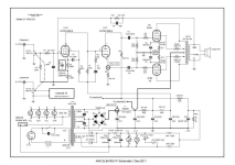
C7, 33pf, and R8, 68k sets the dominant pole, it is at around 71k, so that open loop gain of the amplifier starts tapering off at 71khz at the rate of 6db per octave.....something to do with the output transformer having "funny business" at that frequency...so at71khs, the 68k resistor is is parallel with the 100k plate load resistor of the 6bl8 pentode so that the gain of this voltage amp is reduced by about half that at say 60hz
C9, 68pf, and R7, 10k is an input low pass filter with cornering frequency of 234khz to prevent RFI ingress to the amp, actual corner frequency can be lower due to grid cathode capacitance and some stray capacitance, it is a good value...these parts are important for stability and noise and while the amp will work even without them, still i will not leave those out of the circuit...
btw, "funny business" was defined by the late Patrick Turner as the resonant frequency formed by the leakage inductance and shunt capacitance of the output transformer..so if you know that, you can set the dominant pole t be below such frequency...71khz is way outside or the 20hz to 20khz audio band of frequencies...
Last edited:
I have no clue what you are talking about as does not match the schematic, sorry.C7, 33pf, and R8, 68k sets the dominant pole, it is at around 71k, so that open loop gain of the amplifier starts tapering off at 71khz at the rate of 6db per octave.....something to do with the output transformer having "funny business" at that frequency...so at71khs, the 68k resistor is is parallel with the 100k plate load resistor of the 6bl8 pentode so that the gain of this voltage amp is reduced by about half that at say 60hz
C9, 68pf, and R7, 10k is an input low pass filter with cornering frequency of 234khz to prevent RFI ingress to the amp, actual corner frequency can be lower due to grid cathode capacitance and some stray capacitance, it is a good value...these parts are important for stability and noise and while the amp will work even without them, still i will not leave those out of the circuit...
Wait, are you responding to the first post? If so, then why not seeing it as a different schematic.
I am not sure which transformer is being used.
Why are the C7/R8 and C9/R7 frequencies so high? Why not something just outside the hearing range?
Speaking of hearing range, why a high cut off filter at 68Hz?
I do for the current schematic.so if you know that, you can set the dominant pole t be below such frequency...71khz is way outside or the 20hz to 20khz audio band of frequencies...
All the electrolytic caps I am finding don't even match DIYLC... So far found none that are of the capacitance and/or the voltages specified, usually far more in the case of C9 and 10 (25 volts versus 500 plus). Film caps are in rectangular boxes, however, have short leads. So then use a cap with a voltage rating far in excess and pay three to five times the price? Not being augmentative, simply trying to understand.With point-to-point axial capacitors are a lot easier to work with than radial because they have longer leads at both ends of the body of the component.
Personally myself, don't like C5 being so far, though don't hate it. Better to loose some hundredth of a percent THD then overheat a valve. Though just hit me could put them in the center, then blocks the EL84s from being visible. Axial solve this, however, doesn't seem exist in the specified manner. Even more reason to look forward to your reply! 🙂
What about 15mm and 20mm long leads, longer? https://www.partsconnexion.com/ELNA-72715.html
If not, there are these: https://www.tubesandmore.com/sites/default/files/associated_files/c-jp-cx.pdf.
Seems electrolytic caps are at 20 percent, would have expected 5 percent like resistors. Guess getting obsessed over something that does not matter... Typical of me... 🙄
In the end, appreciative of the suggestion to shorten the length by using much smaller caps, thank you Richard. 😀
Hi Adriel. I am afraid I have completely lost track of what the main focus of this thread should be now. It has drifted a long way from your initial red-line of a pair of monoblocks built point to point.
Please can you state if you have concrete plans to build an amplifier, and what you are planning to build if so. Then I can see if I can contribute further.
I really wish you could be receptive to my advice to buy the Tubelab SPP PCB so that you can build something that is well supported here, as the first step to the more complex monoblocks you set your sights on. The parts you would buy for that are all useful for your future plans, so they are not wasted costs.
Cheers, Richard
these are basic ac analysis of amplifiers, open loop gain, closed loop gains, gain bandwidth or simply bandwidth, and voltage gain is said simply as gain....I have no clue what you are talking about as does not match the schematic, sorry.
Wait, are you responding to the first post? If so, then why not seeing it as a different schematic.
I am not sure which transformer is being used.
Why are the C7/R8 and C9/R7 frequencies so high? Why not something just outside the hearing range?
Speaking of hearing range, why a high cut off filter at 68Hz?
I do for the current schematic.
there is such a thing called dc quiescent biasing or dc operating point, this is what happens to your amplifier when you turn on the power, the ramping up of b+ and filament and thence a few seconds or minutes after when there is no signal yet.. where your plates, cathodes and grids have settled to a certain fixed amounts and hopefully stay there..
how your amp behaves with ac signals is yet another ballgame, a different one..
if you are merely building from an existing design that has been proven to work, then you can ignore my post, they are not for you, but other readers may find something in it...
btw, i find the 1% metal film resistors have gone very low in prices so i use them now in the 0.5 W to 5W ranges, i had several of them smoked, but upon checking the resistances, there were no changes to the value of resistances at all..
why they smoked? due to my carelessness, not checking beforehand what they are actually dissipating...
why they smoked? due to my carelessness, not checking beforehand what they are actually dissipating...
i was commenting on this schematic on post #3...C7, 33pf, and R8, 68k sets the dominant pole, it is at around 71k, so that open loop gain of the amplifier starts tapering off at 71khz at the rate of 6db per octave.....something to do with the output transformer having "funny business" at that frequency...so at71khs, the 68k resistor is is parallel with the 100k plate load resistor of the 6bl8 pentode so that the gain of this voltage amp is reduced by about half that at say 60hz
C9, 68pf, and R7, 10k is an input low pass filter with cornering frequency of 234khz to prevent RFI ingress to the amp, actual corner frequency can be lower due to grid cathode capacitance and some stray capacitance, it is a good value...these parts are important for stability and noise and while the amp will work even without them, still i will not leave those out of the circuit...
btw, "funny business" was defined by the late Patrick Turner as the resonant frequency formed by the leakage inductance and shunt capacitance of the output transformer..so if you know that, you can set the dominant pole t be below such frequency...71khz is way outside or the 20hz to 20khz audio band of frequencies...
Attachments
Interesting you are unable to view my previous posts, I know you would not be so nasty to have me spend hours and hours of work to then deny me the help promised (considering previous conversational transactions). Let me re-post, though shorter, maybe didn't because of a data limit.I am afraid I have completely lost track of what the main focus of this thread should be now.
Why is heater wiring done first?
Instead of using tag strips as said, I am using terminal strips rather than tag strips. However, having trouble finding them and star connectors, know of a source?
So it is clear what I am asking for, here are examples of each.
They were unused slots, what be better the using them for heating wiring?
Besides R7, where else?It looks to me like you have got components going across the same tags of the tag strip - i.e. they are shorted by the tags. For example R7?
As for philosophies concerning hum, I have tried to employ the ones I am aware of, such as one connection to the final ground, any others you would like to generously impart?
Speaking of hum, are you saying you have four grounds attached to the chassis? If so, how did you avoid hum?
What do you mean annotating the valve sockets?
Regarding the Bouyer organ amplifier, DIYLC does not offer solid wire in this manner, requires some fiddling and since not submitting this to an art show, don't plan to involve myself in that endeavor (being somewhat funny if not clear, my humor tends to be dark and dry).
How?It has drifted a long way from your initial red-line of a pair of monoblocks built point to point.
Did you not say to model the layout and promise help with producing a satisfactory result?
Please read either of my responses to this question, the first time I went to great lengths to list it all out and ignored. I am unable to repeat myself for a third time, sorry.Please can you state if you have concrete plans to build an amplifier, and what you are planning to build if so. Then I can see if I can contribute further.
I am at least partly receptive, does that count? 🙂I really wish you could be receptive to my advice to buy the Tubelab SPP PCB so that you can build something that is well supported here, as the first step to the more complex monoblocks you set your sights on. The parts you would buy for that are all useful for your future plans, so they are not wasted costs.
See, I am at least leery of trusting, if not un-trusting, of humans because have been hurt so many times (including child abuse), especially online where so easy to disappear. They say they will help, then when have made the commitment, then disappear. In fact, you have provided an example with your threat. So I go buy all the bits and bobs for the TubeLab, get a question, and then no help forcing me to throw it into the trash (in part because building it to satisfy someone else versus a personal desire). If you can provide a resolution to this, for example mitigating the cost as @oemcar suggested, then will proceed on with the TubeLab.
Let me provide an opportunity to make good on your promise, if you don't mind. I spent hours and hours hunting down axial caps (including three hours to no avail finding them in the 330pF and 680pF values so as can see went back to WIMA) and a couple days compacting plus removing as much wire as possible, resulting in this.
Again, thank you for your past and continued help, certainly appreciated! 😀
Off to break the fast, six grain cereal with mesquite honey (very stout flavor).
Adriel,
Keystone makes stuff for point to point wiring: https://www.keyelco.com/category.cfm/keyelco/Terminals-Terminal-Boards/id/509
Regarding your wiring diagram, it won't work that way. The type of solder terminal strip you show has to have components mounted more like:

That's because the horizontal strips of silver color metal are on each one piece with a hole at each end. The brass part in the middle of the silver strips are rivets to hold the silver color strips down. So part of the each silver piece is hidden under the brass rivet that holds the silver color strip to the green fiberglass board. That can make it hard to see the silver strip is really one piece of metal with a hole left side and another hole on the right side.
It means any component you mount horizontally will be shorted out by the silver strip underneath the component. The circuit just can't work properly that way.
To make it a little more clear, I magnified the picture so you can see there is one horizontal piece of metal per brass rivet. The rivet hides part of the metal underneath. Make sense?

Keystone makes stuff for point to point wiring: https://www.keyelco.com/category.cfm/keyelco/Terminals-Terminal-Boards/id/509
Regarding your wiring diagram, it won't work that way. The type of solder terminal strip you show has to have components mounted more like:
That's because the horizontal strips of silver color metal are on each one piece with a hole at each end. The brass part in the middle of the silver strips are rivets to hold the silver color strips down. So part of the each silver piece is hidden under the brass rivet that holds the silver color strip to the green fiberglass board. That can make it hard to see the silver strip is really one piece of metal with a hole left side and another hole on the right side.
It means any component you mount horizontally will be shorted out by the silver strip underneath the component. The circuit just can't work properly that way.
To make it a little more clear, I magnified the picture so you can see there is one horizontal piece of metal per brass rivet. The rivet hides part of the metal underneath. Make sense?
Last edited:
Thank you for the help! 😀Keystone makes stuff for point to point wiring: https://www.keyelco.com/category.cfm/keyelco/Terminals-Terminal-Boards/id/509
This link nor searching their website does not bring up any terminal strips matching the style shown in your picture. Do you have a part number, please?
Interesting the book shows a style no longer available, creates confusion, especially as both called the same name and/or names swapped. I assumed still available so ignored the connection and used to get an approximate layout.
I am of the persuasion it is best to understand any amplifier you are building, so if understood how your response is related to the question you responded to, then would have value to me, hopefully others understand and find value.if you are merely building from an existing design that has been proven to work, then you can ignore my post, they are not for you, but other readers may find something in it...
Thank you for letting me know. 😀 Only downside is the limited values in flame proofs (I am paranoid due to family and personal experience (wildfire, thankfully skipped over our end of the street)), examples, no 47Ω, only 47,5Ω, though a better example be 820KΩ, nothing remotely close, closest is 825KΩ.btw, i find the 1% metal film resistors have gone very low in prices so i use them now in the 0.5 W to 5W ranges [...]
Though an indirect suggestion, fell in love with this design much to the liking of many (I am being sarcastic): http://www.r-type.org/articles/art-008.htm.
- Home
- Amplifiers
- Tubes / Valves
- Selecting Capacitor(s) and Resistor(s)