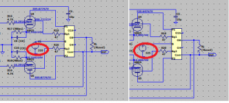
Using this information, I wrote some formulae, allowing folks to see the model as I see it.From the simulation, Vk is at close to 11V. Ik must be Vk/R, so 11/200, so 55mA. Voltage drop across the tube is say Va - Vk, 310V. Dissipation is Ik * (Va - Vk), so approx 17W using estimation.
So here is with the original 270Ω resistor, not enough it seems.
Then the recommended 330Ω resistor.
Resistance has not had a significant impact when consider most folks are unable to hear 0,001 percent distortion. More important, not red plating the tubes.
I would not call modeling fun, it is one of the worse programs I have ever used. The most frustrating is the having to select each command each time, lack of IPTs and OPTs, plus the in-ability to mirror and rotate like CAD. However, it is free and now know to do a layout takes hours, so only did half when realized how late it is.This is a good tool to develop the layout. It is fun to create the parts with the real world sizes. orientate the tube bases and wire it altogether in the drawing tool.
DIYLC
I did the SE as simpler and get some experience before tacking a PP. The only thing is not sure how to model an ECL86, went with worst case, clearly can knock 2"/5cm off, for a 6"/15cm square board. So that part was fun, seeing how small a stereo amplifier can be.Post your results here when you are done so they can be sanity checked before you do it for real.
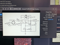
I just got to the page before you deleted both messages, then grabbed another one of your messages, pasted in the text, and still able to quote you. Buhaha. 😛Please hit printscreen instead of taking a photo? Maybe alt-printscreen if you're using Windows? This -->
Then I would have to contend with paint, save it to the flash drive, pull out the flash drive, put it into the Macintosh, open the file, and drop it in. One of the things I loath about Microsoft is the inability to take a screen capture and drag it right into a post. Absolutely hate paint, totally asinine.
Taking a picture does work, does it not?
I saw and saw no point to replying to basically the same post. 🙂I was editing it - check again 🙂
How? Isn't a thumbnail smaller and be even harder to see?Sharing as a thumbnail might help, too.
Another option that crossed my mind is figuring out if can split an incoming fiber optic signal, the router is simply marked "LAN" with no notation of which is what. I don't see the point of paying $50 to have the luxury of internet to the desktop when do 99 percent of internet on the Macintosh; they have a useable wireless unlike Microsoft.
Also, a wifi adaptor is almost free (depending on where you look for it)...
Free from the garbage if you're lucky, or 10$CAD from Bozo : --> https://www.amazon.ca/TP-Link-TL-WN725N-Wireless-Adapter-Miniature/dp/B008IFXQFU
Free from the garbage if you're lucky, or 10$CAD from Bozo : --> https://www.amazon.ca/TP-Link-TL-WN725N-Wireless-Adapter-Miniature/dp/B008IFXQFU
That is why I am puzzled, there are two ports for Ethernet, neither labeled.Doesn't your router have one INPUT (fibre) and several outputs? (WIFI or Ethernet)?
To make it even more fun, there is five cables going from the box to outlets around the house, none of them labeled (the coaxes are, eventually get around to hooking up the FM antenna since now the provider uses fiberoptic, right now on top of the shelving and does okay).
😳 Wow, they sure have come down in price, I remember paying $50 (same as the service charge to hook up the Ethernet). Question is if they are more reliable, the signal was always dropping. For $12 can give it a whirl, sure be nice not having to use a flash dive to transfer files back and forth. In other words, thank you. 😀Free from the garbage if you're lucky, or 10$CAD from Bozo : --> https://www.amazon.ca/TP-Link-TL-WN725N-Wireless-Adapter-Miniature/dp/B008IFXQFU
Sharing as a thumbnail might help, too.

We do have this:
https://www.diyaudio.com/community/...ages-to-your-posts-in-xf.380375/#post-6873448
tbh there will always be instances of something unexpected happening or a user suddenly realising you can do things in a different way. It happens to me all the time on here, always learning you ways and features.
If they have nothing connected, they are probably Ethernet. Connect it and see, you won't blow it up.That is why I am puzzled, there are two ports for Ethernet, neither labeled.
That's called "Sneaker Net" and we used to do it with floppies before networking was common/affordable. 🙂😳 Wow, they sure have come down in price, I remember paying $50 (same as the service charge to hook up the Ethernet). Question is if they are more reliable, the signal was always dropping. For $12 can give it a whirl, sure be nice not having to use a flash dive to transfer files back and forth. In other words, thank you. 😀
When I was 16, I used NAT to share a first gen cable modem with my nextdoor neighbour.
I used a 10 base 2 network (coaxial cable - because it didn't need a hub and I didn't mave the cash for one anyway) between our 486's (80486DX) 🙂
Now, my phone could download the data required to fill the hard disc of that machine in a few seconds... I feel old now.
If that was DiyLC, then I agree is is not perfect, but once you get the hang of it is is very useful for setting the correct physical dimensions of components, selecting tag strips or different circuit board styles, turning the valve bases so they are optimised for heat dissipation, heaters and lastly component planning.I would not call modeling fun, it is one of the worse programs I have ever used. The most frustrating is the having to select each command each time, lack of IPTs and OPTs, plus the in-ability to mirror and rotate like CAD. However, it is free and now know to do a layout takes hours, so only did half when realized how late it is.
Ypu have used real images of tubes in your layout. I would not do that. DIYLC comes with octal and noval tubes bases and you can label the pins. Just lable the pins for the tubes that you are using (for instance a, k, g, h, h, a1, k1, g1 for a dual triode) then use that to get the placement correct.
You have two schematics. In one the output tubes' power supply (V1) is 310V, in the other 325V. That is the reason you get bigger dissipation on the one with V1 at 325V.Interesting, just checked and claiming 15.26W.
I just realized the voltage values in your model differ from mine despite a B plus of 310V, thus why the higher wattage. Weird.

Trouble is knowing what will happen when plug the correct cable in so don't miss it...If they have nothing connected, they are probably Ethernet. Connect it and see, you won't blow it up.
- Home
- Amplifiers
- Tubes / Valves
- Selecting Capacitor(s) and Resistor(s)


