Some parts of those 035ti drivers were made by audax. Not sure who supplied the dome assembly, but the rest of tne motor was audax.I opened a failed dome tweeter from my JBL LSR32 studio monitors and found the pole piece was drilled and filled with what seemed to be a plug of memory foam that seems to fully contact the back of the dome. Those 035TI tweeters have a very flat response and very low distortion.

I can report back with great results and share my technique for magnet disassembly of the most stubborn glue to date. Polk used some sort of Polyurethane glue on these instead of regular Loctite type.
Thanks to George for the tip of not exceeding 180 deg C. to prevent any gauss loss. I brought them up to temp for 20 min.
I just had to lightly tap them with a hammer and punch to dislodge.
I'm hearing smooth, non-fatiguing sound with no sign of resonance at higher volumes on the inexpensive silk domes...
Perhaps someone here can convert one and do A-B comparison on their test equipment. My ears are delighted.
Last edited:
My 2nd set of Wuhan silks are broken in. Wonderful SQ improvement over non-drilled pole-pieces and bare silks. I doped them again using Vit A oil.
... after a long break:
what to do with these tweeters that have a drilled pole piece?
add a 3d printed long (aperiodic) back enclosure, of course!


the graphs are quite self-explaining.
just opening the drilled pole piece hole has a "bass reflex" effect. not very good (mostly for harmonic distorsion).
adding the long back chamber lowers the resonance frequency but introduces resonances, see impedance blips and response wiggles.
filling the long chamber with melamine foam (the magic secret ingredient) removes those resonance effects. it also reduces the resonance frequency peak. the chamber was not stuffed entirely, so the remaining wiggles in the response graph will probably be reduced with added melamine foam.
(response graphs taken on axis with 1 V rms input and 25 cm microphone distance, tweeter mounted not centrally on a flat 50/100 cm baffle)
what to do with these tweeters that have a drilled pole piece?
add a 3d printed long (aperiodic) back enclosure, of course!
the graphs are quite self-explaining.
just opening the drilled pole piece hole has a "bass reflex" effect. not very good (mostly for harmonic distorsion).
adding the long back chamber lowers the resonance frequency but introduces resonances, see impedance blips and response wiggles.
filling the long chamber with melamine foam (the magic secret ingredient) removes those resonance effects. it also reduces the resonance frequency peak. the chamber was not stuffed entirely, so the remaining wiggles in the response graph will probably be reduced with added melamine foam.
(response graphs taken on axis with 1 V rms input and 25 cm microphone distance, tweeter mounted not centrally on a flat 50/100 cm baffle)
By the way: the dip of driver output at the tuning frequency of 850 Hz is where the "port" on the back side has it's max output, of course. Still not useful ...just opening the drilled pole piece hole has a "bass reflex" effect.
Excellent work and great documentation. I spent a lot of time between 2016 and 2020 working with the Aurasound 1" and 2" full range drivers that have a large hole in what is the pole piece. No drilling required. I started experimenting with PVC pipe and thick automotive rubber heater hose. As I was dealing with 40 drivers I bought a 50 foot roll of the stuff. For fun I attached the end of the whole roll to one driver. The response was perfect. I settled on 18" of hose for each driver stuffed with pellets of a quality acoustic foam that's sold for use on studio walls etc. On later builds I found that stuffing fiberglass in a tube was much more effective than the foam due to the higher density I could achieve. So I was able to get good results with the 2" driver using a 6" segment of iron plumbing pipe stuffed with fiberglass. All that to say, you might try using fiberglass in your chamber. You can vary the density and see how it goes. I would go with low density near the driver and increase it to the rear of the chamber on my 2" drivers, so they had some volume that didn't push the resonant frequency too high.
It is interesting to see the resonances with the chamber empty vs. stuffed to see what the resonance peaks look like.
I don't have such nicely organized documentation as STV in the previous post, but I found a few graphs from experiments with PVC pipe.
The driver was close mic'd and not on any baffle.
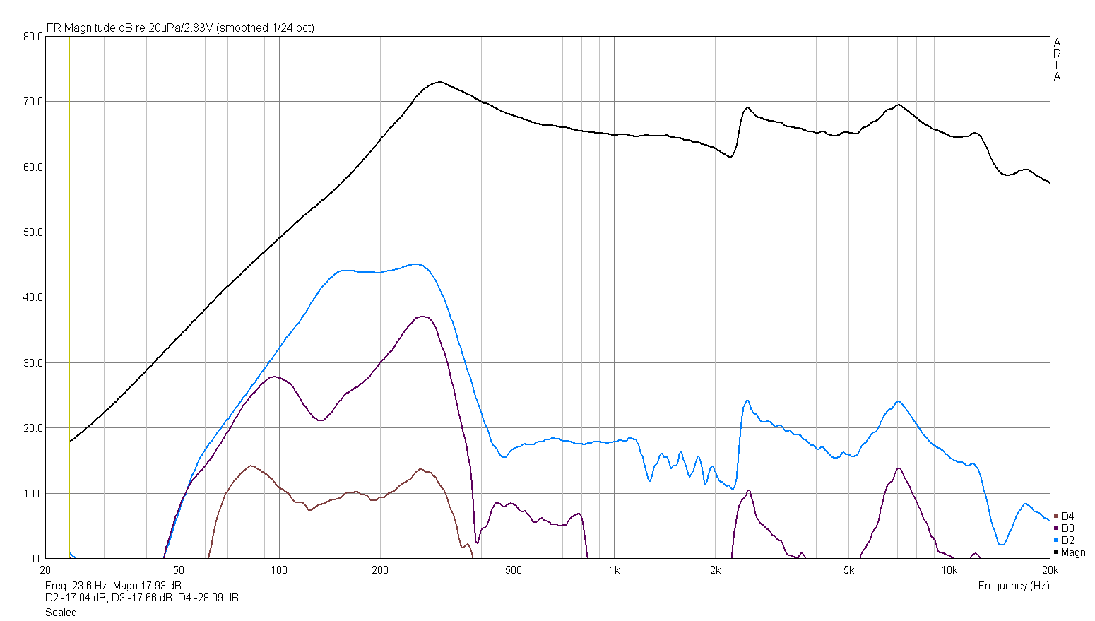
Figure 1. Aurasound Cougar with empty 1" ID, 2" long PVC pipe attached to rear as enclosure.
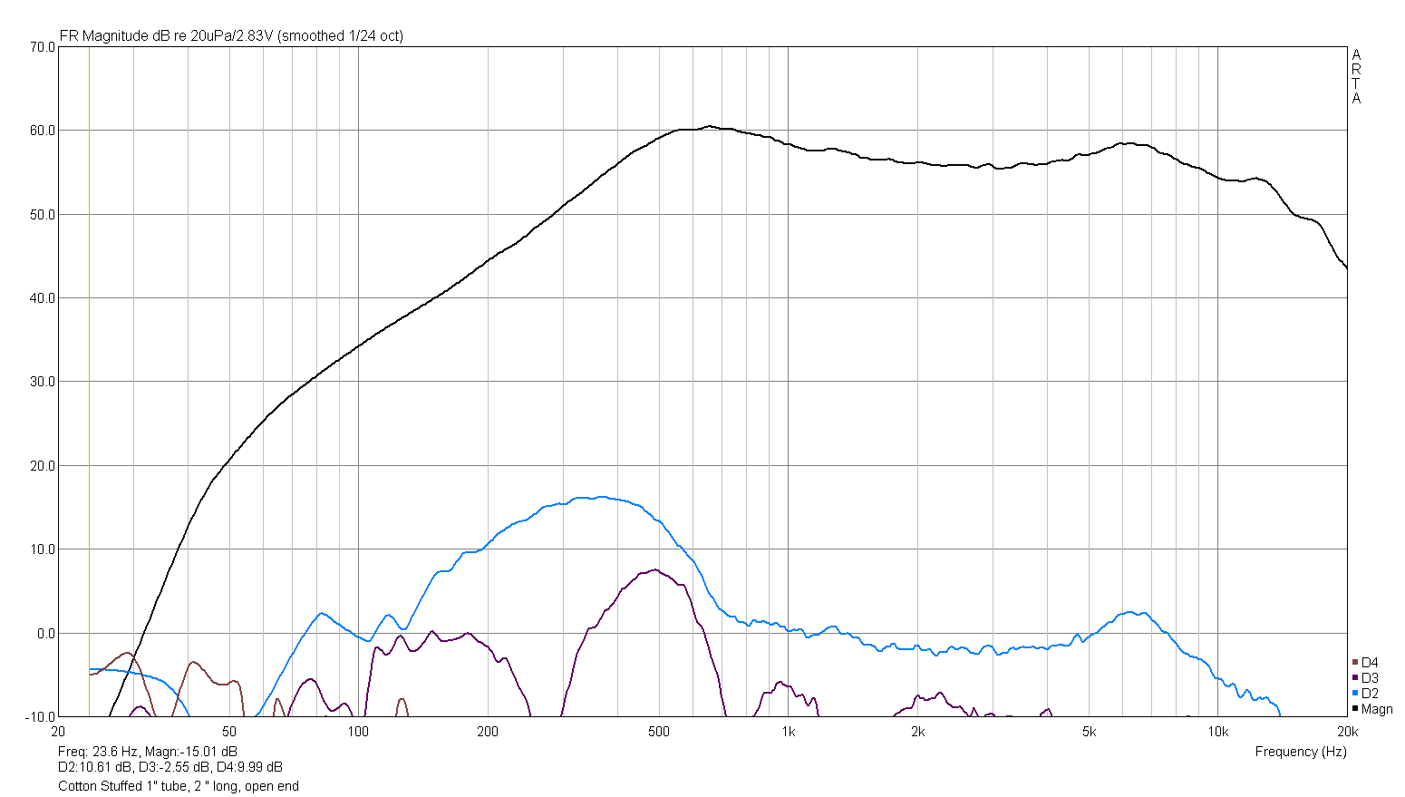
Figure 2. Aurasound Cougar with cotton stuffed 1" ID, 2" long PVC pipe attached to rear as enclosure.
Note that the reflection / resonant peak at 2.3 kHz is gone and the distortion is 55 dB down.
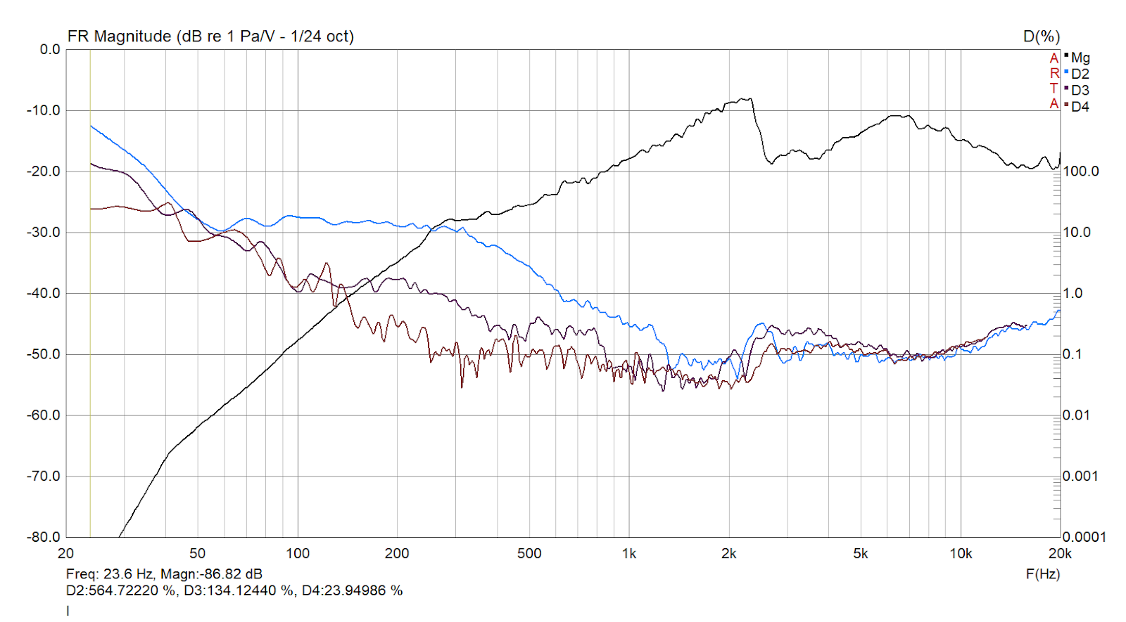
Figure 3. Aurasound Cougar 1" full range close mic bare driver with no baffle and no rear enclosure. It measures very poorly this way as it is open baffle, so the rear wave is coming around and the lack of enclosure leaves just a truncated tube behind the dome with reflections.
It is interesting to see the resonances with the chamber empty vs. stuffed to see what the resonance peaks look like.
I don't have such nicely organized documentation as STV in the previous post, but I found a few graphs from experiments with PVC pipe.
The driver was close mic'd and not on any baffle.
Figure 1. Aurasound Cougar with empty 1" ID, 2" long PVC pipe attached to rear as enclosure.
Figure 2. Aurasound Cougar with cotton stuffed 1" ID, 2" long PVC pipe attached to rear as enclosure.
Note that the reflection / resonant peak at 2.3 kHz is gone and the distortion is 55 dB down.
Figure 3. Aurasound Cougar 1" full range close mic bare driver with no baffle and no rear enclosure. It measures very poorly this way as it is open baffle, so the rear wave is coming around and the lack of enclosure leaves just a truncated tube behind the dome with reflections.
Last edited:
... after another long break and just to document some more exciting experimental modifications (so you don't have to do them yourself!):
I cut the plastic supports with a small dremel cutting tool:

this exposes the very delicate aluminium dome, the SEAS 25TAF/D dome material is a very soft alloy.
eventual dents can be pushed out from behind, but it's better not to make any!

I removed the outer phase plug ring to also test only the central piece:

tweeter without phase plug, installed flush into a big (100/50 cm) baffle, in a small, handmade (non very optimized) waveguide and in the WG with cenrtal phase plug:


here are the frequency responses (gated, at about 40 cm distance, low voltage - not 2,83 V!):
1) installed flush in the baffle with the original phase plug (not shown in photo) ...

2) .... flush in the baffle without any phase plug construction ...

3) .... now in the WG with original phase plug (note that the falling response slope is inherent to uncorrected WG) ...

4) ... in the WG with only the central phase plug (not advisable!) ....

5) ... and in the WG without all phase plug elements:

the last response shows that the non-phase plug version may eventually be better suited for a wave guide, but the WG still needs to be optimized, mostly the transition from dome/surround to the WG shape. covering the surround or making a small step at the WG throat may solve the on-axis dip at 15 kHz.
As I wrote above, the dome is very soft and prone to denting or scratching.
So how to solve this problem in case we don't want to have the protecting phase plug?
Right!!!
(yes, I know it's crazy, but my curiosity was stronger!)
anodising is not a completely harmless process, so do it at your own risk and do a thorough research.
gloves, safety goggles and a ceramic container ... you know.
very gently sanding the dome for a smooth surface:

a plastic container just big enough for the dome to dip into a ~15% sulfuric acid (more than 15% is not generally available) and using a lab supply with around 20 - 30 V DC, negative plug connected to a base metal cathode in the acid (piece of soldering wire), positive plug connected to the dome:


I really would not do that again, but if I did, I would turn the whole construction by 180°.
The current flow was not evenly spread over the dome and the transformation from metal to ceramic material was not even at all.
In fact there was a small spot where all the aluminium turned into extremely brittle "transparent aluminium":

this spot disintegrated at the first touch and I had to "repair" it by gluing a small piece of aluminium foil from the back.
But still, the rest of the dome got a matte light grey anodised surface that is in fact quite resistant to scratching.
Here are the resulting on-axis response graphs, this time done with high sample rate to capture the ultrasonic effects.
This includes:

you can see a small perforation effect between 2 and 4 kHz.
the graph also shows that the phase plug reduces the resonance peak at around 26 kHz.
anodising increased that resonance peak - so it seems the guys at SEAS did indeed know what they were doing when chosing the soft low resonance material!
repairing the perforation evened out the audible range, but amplified and lowered the frequency of a second breakup resonance at 20 kHz.
anodising for less delicate elements does work quite well, but it heavily depends on the specific alloy.
by the way: I got a replacement front plate with dome from TLHP!
what happens if I (partially or completely) remove the tweeter's phase plug?
I cut the plastic supports with a small dremel cutting tool:
this exposes the very delicate aluminium dome, the SEAS 25TAF/D dome material is a very soft alloy.
eventual dents can be pushed out from behind, but it's better not to make any!
I removed the outer phase plug ring to also test only the central piece:
tweeter without phase plug, installed flush into a big (100/50 cm) baffle, in a small, handmade (non very optimized) waveguide and in the WG with cenrtal phase plug:
here are the frequency responses (gated, at about 40 cm distance, low voltage - not 2,83 V!):
1) installed flush in the baffle with the original phase plug (not shown in photo) ...
2) .... flush in the baffle without any phase plug construction ...
3) .... now in the WG with original phase plug (note that the falling response slope is inherent to uncorrected WG) ...
4) ... in the WG with only the central phase plug (not advisable!) ....
5) ... and in the WG without all phase plug elements:
the last response shows that the non-phase plug version may eventually be better suited for a wave guide, but the WG still needs to be optimized, mostly the transition from dome/surround to the WG shape. covering the surround or making a small step at the WG throat may solve the on-axis dip at 15 kHz.
As I wrote above, the dome is very soft and prone to denting or scratching.
So how to solve this problem in case we don't want to have the protecting phase plug?
Right!!!
Let's anodise the dome and turn it into a super hard ceramic material (at least the surface)!
(yes, I know it's crazy, but my curiosity was stronger!)
anodising is not a completely harmless process, so do it at your own risk and do a thorough research.
gloves, safety goggles and a ceramic container ... you know.
very gently sanding the dome for a smooth surface:
a plastic container just big enough for the dome to dip into a ~15% sulfuric acid (more than 15% is not generally available) and using a lab supply with around 20 - 30 V DC, negative plug connected to a base metal cathode in the acid (piece of soldering wire), positive plug connected to the dome:
I really would not do that again, but if I did, I would turn the whole construction by 180°.
The current flow was not evenly spread over the dome and the transformation from metal to ceramic material was not even at all.
In fact there was a small spot where all the aluminium turned into extremely brittle "transparent aluminium":
this spot disintegrated at the first touch and I had to "repair" it by gluing a small piece of aluminium foil from the back.
But still, the rest of the dome got a matte light grey anodised surface that is in fact quite resistant to scratching.
Here are the resulting on-axis response graphs, this time done with high sample rate to capture the ultrasonic effects.
This includes:
- original dome with complete phase plug element.
- original dome without phase plug element.
- anodised and perforated dome withoug phase plug
- repaired anodised dome without phase plug.
you can see a small perforation effect between 2 and 4 kHz.
the graph also shows that the phase plug reduces the resonance peak at around 26 kHz.
anodising increased that resonance peak - so it seems the guys at SEAS did indeed know what they were doing when chosing the soft low resonance material!
repairing the perforation evened out the audible range, but amplified and lowered the frequency of a second breakup resonance at 20 kHz.
anodising for less delicate elements does work quite well, but it heavily depends on the specific alloy.
by the way: I got a replacement front plate with dome from TLHP!
Last edited:
distorsion graphs for the original dome (without phase plug and waveguide), for the perforated "version" and the repaired one.
apologies for the distorsion graphs mostly buried in noise, this is just for comparison!


it was to be epected that the damaged, perforated dome would have lots of distorsion due to uncontrolled edge vibration and maybe even some sort of helmholtz resonance.
but I am quite surprised that my rudimentary repair job worked so well!
apologies for the distorsion graphs mostly buried in noise, this is just for comparison!
it was to be epected that the damaged, perforated dome would have lots of distorsion due to uncontrolled edge vibration and maybe even some sort of helmholtz resonance.
but I am quite surprised that my rudimentary repair job worked so well!
Very nice work/addition of the backwave chamber. How did you come to conclusion/calc of the backwave chamber shape?... after a long break:
what to do with these tweeters that have a drilled pole piece?
add a 3d printed long (aperiodic) back enclosure, of course!
View attachment 1240895
View attachment 1240898
View attachment 1240897
the graphs are quite self-explaining.
just opening the drilled pole piece hole has a "bass reflex" effect. not very good (mostly for harmonic distorsion).
adding the long back chamber lowers the resonance frequency but introduces resonances, see impedance blips and response wiggles.
filling the long chamber with melamine foam (the magic secret ingredient) removes those resonance effects. it also reduces the resonance frequency peak. the chamber was not stuffed entirely, so the remaining wiggles in the response graph will probably be reduced with added melamine foam.
(response graphs taken on axis with 1 V rms input and 25 cm microphone distance, tweeter mounted not centrally on a flat 50/100 cm baffle)
I experimented with back-chambering some older Polk tweeters with their factory silk domes and inexpensive aftermarket silk replacements. It indeed cleared/smoothed the cheap aftermarket silks using lamb's wool in the chambers.
no calculation, it was just a shape and dimension that felt right.How did you come to conclusion/calc of the backwave chamber shape?
I had the pole drilling diameter and wanted to make a slightly curved converging back chamber, considering a potential first resonance to be below potential crossover frequency around 2 kHz.
but anyway the resonance will be mostly absorbed once the back chamber is completely filled with absorbing material.
making the aperiodic absorber tube even longer is probably better.
Really great work and documentation. Bummer with the hole in the dome. I have been looking at the five fin phase plug sort of almost a tiny segmented horn that KEF puts in front of their dome tweeter. I assume it is responsible for the very wide dispersion that they get from a 1" dome all the way up to 18 kHz or so according to tests by Erin's Audio Corner youTube channel. I don't recall seeing such a wide high frequency pattern from any other 1" dome. I hope to 3D print and test something like that in the next few months when the weather isn't so nice.

- Home
- Loudspeakers
- Multi-Way
- SEAS tweeter pole piece drilling