Hi,
Was looking at the SEAS driver... came across this thread.
I was curious about your new design. Did you remove the original bracing?
Was looking at the SEAS driver... came across this thread.
I was curious about your new design. Did you remove the original bracing?

@gcl
I thought about your design... Its like the side panels are like 1/2 an airfoil.
If you had access to a CNC router or laser... would you consider doing the side panels as a translam? And where you'd have your braces they would be part of your panel? This would give you a continuous curve on the outside along w the ability to change the panel thickness?
I guess it would be more for aesthetics.
Definitely a cool mod to their design.
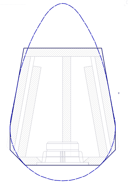
Sorry, I have not been around here for a while. There are no plans in the form I can attach. I made sketches and calculations in my note book and built from paper and card templates. I have attached the original plan shape marked up with dimensions of the finished enclosure. The front and back are double thickness 18mm ply. As are the top and bottom. The total height is 1020. As you can see in the photos there are four pairs of braces which the sides were built on to. The sides were built up from individual pieces of 18mm ply. As described they were lined with rubber, 8-9mm thick ceramic tiles, (no particular pattern!) and then 15mm wool felt blanket which makes the sides very dead and sound absorbing. Hope this helps.Very curious about this design, would you be willing to share the plans?
Attachments
The plan view looks to be the same shape as my trapezoidal miniOnkens, with a teardrop approximation.
From the sketch i would suggest your bracing could be better. For one they should run vertically to satisfy this general rule of bracing: the aspect ratio of the subpanels created by the braces should be higher than the aspect ratio of th epanel being braced.
The braces should also reach all the way across the box, extending the vertical bits across the box and lose the horizontal ones. I also like to brave teh back of the driver against the back and top.
Double bottom likely unnecessary.
Do note that given the aspect ratio wthis will be a quarterwave box, so it can’t be modeled as a bass reflex.
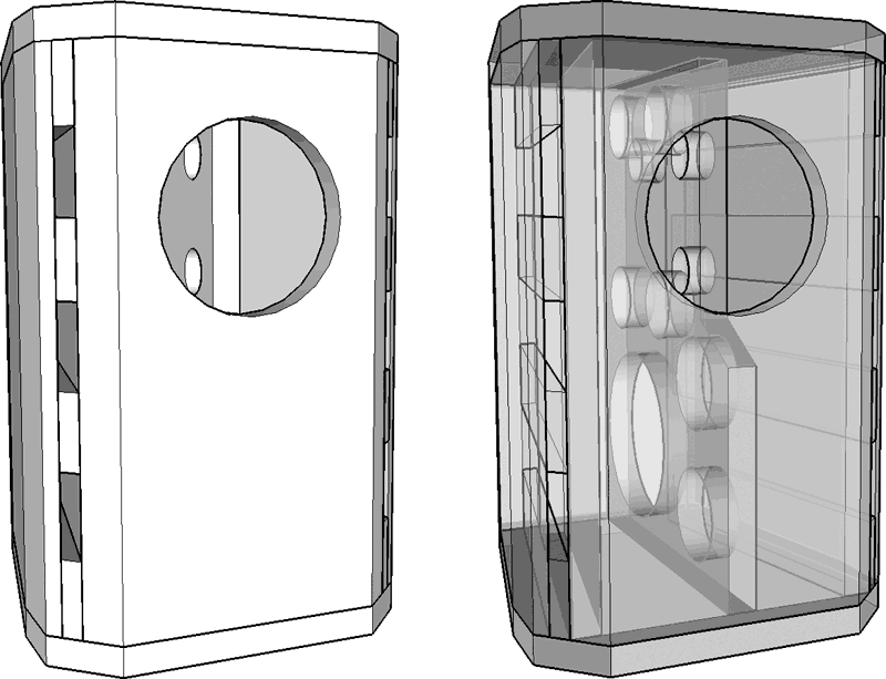
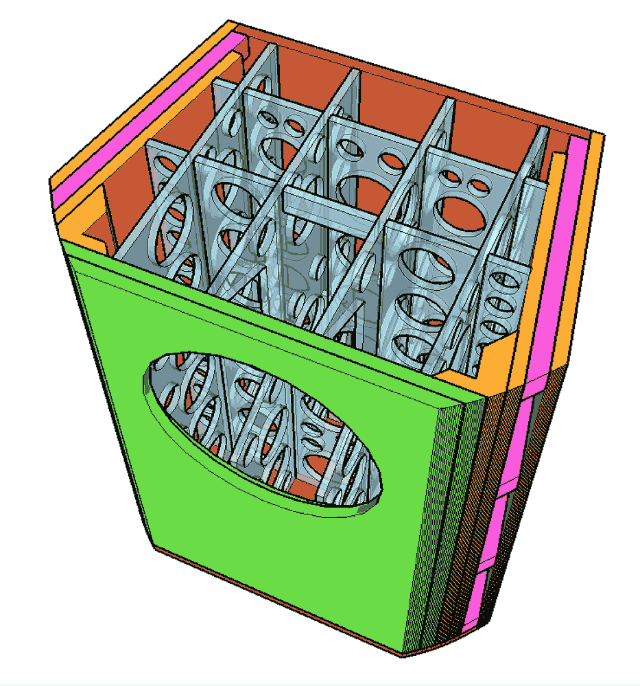
I have literaly 100s of these trapezoids, this is the visualization (for a much smaller box) which shows th eminimal bracing — note that the “triple” sides accommodating the vents is a naturally braced panel. In larger ones the bracing gets more extensive.
dave
Thick is the brute force method and i do not think trumps clever engineering design. Light & stiff & engineered.
The braces developed somewhat after building some and testing for resonances with a mechanics stethescope.
Partially it depends on the bandpass of the driver into the box, with the SEAS it is FR so you don’t get any breaks. Every 15-20 cm is probably a decen rule-of-thumb. With the driver braced against more panels much of the source of energy to drive resonance is now shared across 4 panels and the brace(s) itself so the energy that needs to be damped, or otherwise dissipated is a smaller amount (per panel volume).
dave
Last edited:
- Home
- Loudspeakers
- Full Range
- SEAS EXOTIC F8 speaker build