The benefit of super beta transistors is for applications where you need a very low input offset voltage.
On this quest, the first step is looking for low Vos Op Amps. Then you realize that you need low Ios as well.
So you bump on the dilemma: FET input has low Ios but bad Vos. Bipolar input has low Vos but bad Ios. And you comprise with impedances as low as feasible.
Thanks to super beta transistor you have a neat solution. Low Ios and low Vos.
And the Op Amps do exist.
Thanks to contributors for the links given in this thread, that gather a lot of interesting informations.
"Interesting" that TI implies they discovered this [superbeta BJTs in opamps] recently.
Embarrassing is more like it. The youthful apps engineers who write app notes weren't tutored by the graybeard TI Fellows who built and used LM108-era parts. And if any TI employee of any age, bothered to google "Superbeta AND IEEE" (here's a link, try it yourself) , they didn't pass the results along to the authors.
Oups....I am not sure of that...The benefit of super beta transistors is for applications where you need a very low input offset voltage.
On this quest, the first step is looking for low Vos Op Amps. Then you realize that you need low Ios as well.
So you bump on the dilemma: FET input has low Ios but bad Vos. Bipolar input has low Vos but bad Ios. And you comprise with impedances as low as feasible.
Thanks to super beta transistor you have a neat solution. Low Ios and low Vos.
And the Op Amps do exist.
So far I found LM101, with a terrible Vos by today's standards.
In other words: I have not found better than OPA277.
Last edited:
If you seek a minimalist, low-parts-count design for a linear power supply as suggested in post #4, then an LM7818 cascaded with an opamp + series pass transistor + shunt reference will perform well. The upstream LM7818 boosts PSRR by 50 dB at the cost of two inexpensive & small components. The downstream regulator gives super low output impedance (thanks to >80dB of gain in the opamp) and super low noise (thanks to LPF on VREF).
Yes, this is a way to do the #4 post suggestion.
Shunt reference + Op amp. You have it inside a TL431.
There are several ways to skin a cat.
Rather than cascading a LM1818 ( a fixed 18V series regulator ) to obtain a 50dB improvement, one can Darlingtonize the pass transistor adding a dirt cheap low power bjt ( plenty have Beta > 350 ). This gives +50 dB loop gain, that does the improvement.
Wow, +50dB loop gain from two emitter followers in series! And I thought each emitter follower has a voltage gain of 0.99X, meaning that a cascade of two will have a voltage gain of 0.98X. Better check those textbooks again.
If I did the arithmetic correctly, +50dB loop gain is 316X. From two emitter followers in series!
If I did the arithmetic correctly, +50dB loop gain is 316X. From two emitter followers in series!
You will NOT work "well below 1mA".Bjts have Beta droop at low current.
How bad, is this ?
What low power transistors have good Hfe at collector currents well below 1mA ?
For your stated 100mA power supply, suppose you use a TIP31 pass transistor, minimum Hfe will be around 80
Suppose you want a safety margin just in case you got a bottom of the barrel one, assume Hfe=50
So base current (which will be its drive transistor Collector current) will be 2 mA, definitely not "well below 1mA"
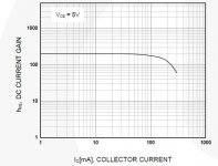
Using a BC548 transistor, as generic as can be, its own Hfe is ruler flat at such currents:
[see attached image below]
so no need at all to search for "special" devices for such a plain vanilla circuit.
Attachments
Last edited:
Indeed, but neither is low-noise. In fact, they have a rather high noise.Yes, this is a way to do the #4 post suggestion.
Shunt reference + Op amp. You have it inside a TL431.
A good (thus relatively expensive) opamp is required, in addition to a filtered reference.
Even better than a good opamp is a regular BJT, like in the denoiser
Others have already answered.There are several ways to skin a cat.
Rather than cascading a LM1818 ( a fixed 18V series regulator ) to obtain a 50dB improvement, one can Darlingtonize the pass transistor adding a dirt cheap low power bjt ( plenty have Beta > 350 ). This gives +50 dB loop gain, that does the improvement.
Earlier, I also compared the voltage gain of a single transistor and a darlington.
Just for the fun of it, I attempted this measurement:
Believe it or not, I got a (somewhat flaky) result.To measure below, one could put the DUT as a driver to a known transistor in a Darlington configuration.
With an Ic of 400pA, the base current is somewhere between 3 and 4pA, thus a Hfe of ~100 (+/-50%).
The measurement drifted all over the place, because I didn't take many precautions, but the difference between the current with the 44Meg load in circuit, then removed was consistent enough.
Ideally at this sensitivity level, the whole setup should be enclosed in a metallic, hermetic box to minimize temperature gradients, drafts and electrostatic influences. As this was not the case, just looking at the circuit caused it to drift, but one thing is certain: the Hfe remains quite high at the pA level, even with a cheap transistor (the input one was also the same S9014)
...So far I found LM101...
That's even older than LM108. There has been some advance over the 50+ years. Keep looking.
(While now obsoleted, the old LM108/308 is still a fine choice for most "precise" DC, and certainly for audio DC "precision". Except the guitar-pedal crowd has bid them up past where fakes appear.)
The last time I tried to measure picoamp currents at home (74AHCU04 input currents) and got funny results, it took a while before I realized I was actually measuring rectified mains hum picked up by wires connected to a high-impedance node. PCB leakage is usually no problem as long as the PCB is clean and dry and the voltage low, at university I've made circuits working with 10 pA bias currents and supply voltages in the 1 V to 3 V range on plain pertinax perfboard.
A trouble with information dug from internet, is that it can be outdated, with no date and looking new.That's even older than LM108. There has been some advance over the 50+ years. Keep looking.
(While now obsoleted, the old LM108/308 is still a fine choice for most "precise" DC, and certainly for audio DC "precision". Except the guitar-pedal crowd has bid them up past where fakes appear.)
LM108/308 not available via Octopart.
Last edited:
High beta goes at the expense of lower breakdown (-> PRR) for sure. How else to get those stubborn electrons moving en masse?
Now, within this very topic, I require serious opinions about using (TTA/TTC) 1943-5200 as drivers for (TTA/TTC) 1943-5200 in a Sziklai configuration, driven from the input stage by humble BC550C/BC560C's. Think a Hirage amplifier setup. Simu's say yes-no problem. All about high beta & 'low' current. PS=+/-15V, bias@1A. TIA.
Now, within this very topic, I require serious opinions about using (TTA/TTC) 1943-5200 as drivers for (TTA/TTC) 1943-5200 in a Sziklai configuration, driven from the input stage by humble BC550C/BC560C's. Think a Hirage amplifier setup. Simu's say yes-no problem. All about high beta & 'low' current. PS=+/-15V, bias@1A. TIA.
Earlier, I also compared the voltage gain of a single transistor and a darlington.
Yeah, the darlington will not be of much improvement of the ripple rejection, since it is dependent on the voltage gain. At the most you gain 20dB by increasing the resistor 10 fold.
But another 100uF on the output will. This cannot be done with an integrated regulator because of stability.
you get -40dB at 100Hz and -60dB at 1k
Now if you add another stage -80dB at 100Hz. This is the most efficient., takes only 4V away.
Last edited:
Yes superbeta's time has come, and gone. High volume customers can get (much) better performance without superbeta, so the demand for superbeta has dropped below the threshold of profitability. Goodbye and farewell, superbeta. Killed by George Erdi (citation)
- Home
- Design & Build
- Parts
- Search for BGTs with high Beta at low current