Yes. It is clear it makes sense only for circuits where current gain does matter.Circuits depending on the transconductance rather than current gain are going to be degraded instead.
Such a circuit is typically an emitter follower where going 2EF, even 3EF gives an immediat improvement.
A 3 bit combo, I am thinking of is the very old regulated power supply topology that was simply using a zener and a pass transistor.
The pass transistor being made of 3 bjts in this configuration: Power transistor and driver in a Darlington configuration and over this pair a predriver of opposite polarity in a CFP configuration.
Obviously, this better needs a pre driver bjt with little beta drop at very low current.
Hi @bansuri; Linear Systems has two distributors in the USA for customers like me who are also in the USA: Trendsetter, and NACsemi. Unfortunately neither of them has any LS301 parts in stock. They don't even have a sales page for the LS301. Same goes for LS302 and LS303.
Maybe other distributors in other regions of the world, do have some LS301s to sell. I hope so!
Maybe other distributors in other regions of the world, do have some LS301s to sell. I hope so!
And if you're thinking of using a Pchannel JFET, either for an LDO positive regulator or a standard negative regulator: quite a few of them are still in active production and are on the shelf, ready to "dispatch", ... in surface mount packages.Just a reminder: nothing beats (MOS-)FETs when you want a really high current gain.
Mark, it requires a bit of search to find superbeta transistors, I just wanted to show these parts exist. Commercially available with beta up to 3500. Research says it will be possible to 30000 with a single junction.
Some opamps have superbeta fromt ends
Some opamps have superbeta fromt ends
I have also noticed that modern transistors, even cheap ones behave rather well at low Ic.Nexperia BC847 transistors have far less hFE drop at low currents than I remember of their predecessor Philips BC547:
https://assets.nexperia.com/documents/data-sheet/BC847_SER.pdf
Improved annealing or so?
Philips BC550B, August 1987 datasheet:
hFE typ. 150 at 10 uA, 290 at 2 mA
Nexperia BC850B, January 2004 datasheet:
hFE typ. 240 at 10 uA, 290 at 2 mA
Nexperia BC847B, October 2019 datasheet:
hFE typ. 280 at 10 uA, 290 at 2 mA
There is a reduction, of course but Hfe>100 @Ic<1µA remains perfectly usable.
There are exception though: phototransistors. They become practically blind at low luminous intensities, probably because of the geometry.
To keep the transistor effect at low level, it is necessary to apply some initial bias, electrical if the base is accessible or optical if it isn't
From internet searches, my understanding:Mark, it requires a bit of search to find superbeta transistors, I just wanted to show these parts exist. Commercially available with beta up to 3500. Research says it will be possible to 30000 with a single junction.
Some opamps have superbeta fromt ends
Super beta transistor do exist in some ICs.
They need added protection circuitry, so not likely to be usable as discrete parts.
There are confusions with "super beta transistor" used as an alternate name to "Darlington".

Do not play with name, confusing Apple and Oranges.
TTC007 is a high beta transistor, Hfe 400 1000.
It is not a super beta transistor with Hfe well beyond 1000.
I see TTC007 has base emitter limit 7V, this means it is a classic bjt that doesn't need special protections as needed by the true super beta transistors because they have extremely thin BE junction.
Post #23 is gently suggesting the "fetlington" topology, which is eminently practical in both genders, if you're willing to do (post #25). JFET source follower --> BJT emitter follower. Gigohms of input impedance thus nanoamps of input current into the control terminal. Equivalent Beta (Iout / Icontrol) of at least one million.
There are lots of resources to learn about JFETs, here's an excellent textbook on Google Books: Fet Technology and Application - E. S. Oxner - Google Books for example
The gate of a JFET is just a diode; and on a silicon JFET it's a silicon diode. I myself fitted the spice parameters of a JFET gate diode, the NXP BF862:

_
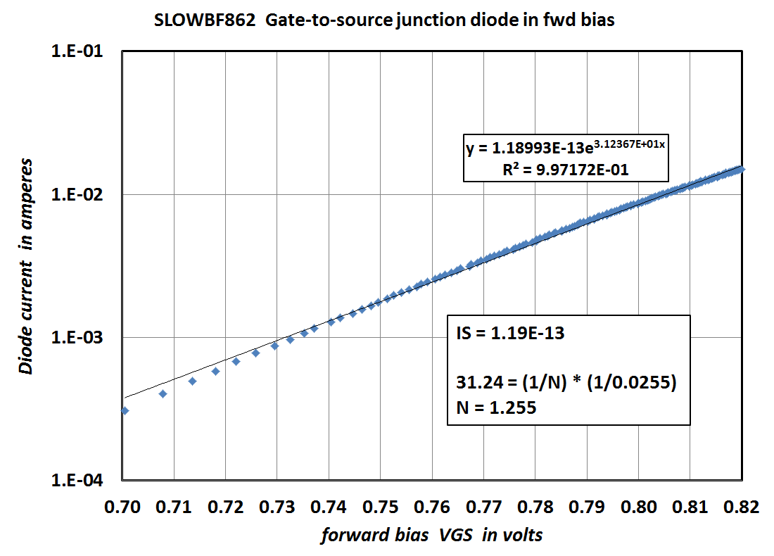
Each of the light blue diamonds is a measured datapoint (from the LockyZ curve tracer) and the black line is Excel's best fit via linear regression. The output from Excel is in the upper box, and the spice parameter fitting (parameter names "IS" and "N") calculations are in the lower box.
It's all in post #1 of this thread
https://www.diyaudio.com/forums/solid-state/296335-ltspice-models-worst-bf862-jfets.html#post4821746
I'm sure folks like Elvee would also be glad to suggest helpful JFET tutorials.
The gate of a JFET is just a diode; and on a silicon JFET it's a silicon diode. I myself fitted the spice parameters of a JFET gate diode, the NXP BF862:
_
Each of the light blue diamonds is a measured datapoint (from the LockyZ curve tracer) and the black line is Excel's best fit via linear regression. The output from Excel is in the upper box, and the spice parameter fitting (parameter names "IS" and "N") calculations are in the lower box.
It's all in post #1 of this thread
https://www.diyaudio.com/forums/solid-state/296335-ltspice-models-worst-bf862-jfets.html#post4821746
I'm sure folks like Elvee would also be glad to suggest helpful JFET tutorials.
A FET is a voltage-controlled device; the input current is normally negligible.
I have just measured a dirt-cheap, Chinese (but recent) S9014.
At Ic=1mA, the Hfe is 330, quite normal, and at Ic=100nA it drops to 250, which remains perfectly acceptable.
This is the test circuit I used for the low current measurement.
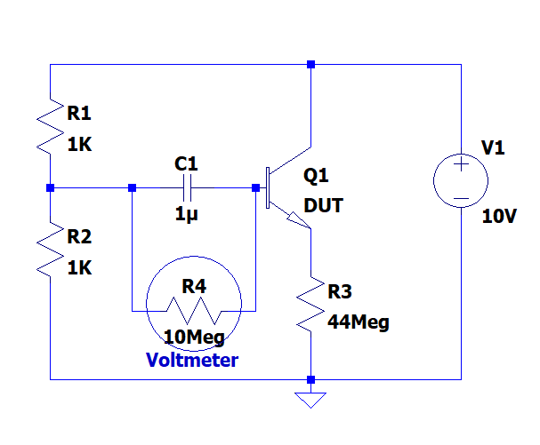
It is easy to reproduce
I have just measured a dirt-cheap, Chinese (but recent) S9014.
At Ic=1mA, the Hfe is 330, quite normal, and at Ic=100nA it drops to 250, which remains perfectly acceptable.
This is the test circuit I used for the low current measurement.
It is easy to reproduce
Attachments
Good to see reliable data at 0.1μA Ic.
That must be pretty tought to deal with 44 MegOhm resistors.
To measure below, one could put the DUT as a driver to a known transistor in a Darlington configuration.
That must be pretty tought to deal with 44 MegOhm resistors.
To measure below, one could put the DUT as a driver to a known transistor in a Darlington configuration.
This is a real interesting and recent pdf by TI
https://www.ti.com.cn/cn/lit/an/sboa305/sboa305.pdf
The only difference to normal transistors is that the Ube reverse voltage should not exeed 6.2V, when the zener action with avalance break-through happens.
This is hardly an issue in a front-end circuit. A diode can prevent that.
https://www.ti.com.cn/cn/lit/an/sboa305/sboa305.pdf
The only difference to normal transistors is that the Ube reverse voltage should not exeed 6.2V, when the zener action with avalance break-through happens.
This is hardly an issue in a front-end circuit. A diode can prevent that.
> interesting and recent pdf by TI
The SuperBeta input concept goes back over 50 years to Bob Widlar.
https://pe2bz.philpem.me.uk/Parts-A...ional/AN-29-OpAmp-BeatsFET-onInputCurrent.pdf
Superbeta transistors inside: Die photos and analysis of the LM108 op amp
We know from (Grove? Shockley?) that best beta goes about as square-root of junction breakdown, so a 800V BJT has hFE like 30, a 8V BJT may be 300, and a sub-volt BJT can have hFE over 1,000. (Hitting these theoretical limits may be uneconomic.)
"Interesting" that TI implies they discovered this recently.
Last edited:
The only difference to normal transistors is that the Ube reverse voltage should not exeed 6.2V, when the zener action with avalance break-through happens.
This is hardly an issue in a front-end circuit. A diode can prevent that.
That's not a difference; normal transistors can also just handle 1 V (fast RF transistor) ...5 V (general purpose transistor) in reverse across the base-emitter junction and their hFE and 1/f noise degrades when you exceed that.
44 Meg is still easily manageable (2 x22 Meg), and indeed now that we know that the base current is 0.4nA, it can be used to load a darlington stage in front.That must be pretty tought to deal with 44 MegOhm resistors.
To measure below, one could put the DUT as a driver to a known transistor in a Darlington configuration.
At this level, some more precautions will be required to obtain a stable measurement
- Home
- Design & Build
- Parts
- Search for BGTs with high Beta at low current