Bjts have Beta droop at low current.
How bad, is this ?
What low power transistors have good Hfe at collector currents well below 1mA ?
How bad, is this ?
What low power transistors have good Hfe at collector currents well below 1mA ?
Wrong term - beta droop is what happens at high current, on the right-hand side of the beta(Ic) graph.
At low currents,
a) beta drops off due to leakage and
b) fT drops off due to input capacitance (Ccb in particular).
If you need <<1 mA, you should be looking at traditional "low-noise" transistors - think BC550/560, 2SC945, KSC1845/KSA992, 2SC2240/2SA970, depending on what kind of Vceo you need. These should generally be good for around 10 µA if need be. They're not exactly Rbb' champs but this doesn't matter a whole lot at these kinds of currents. Ccb usually isn't anything particularly low.
Input nonlinearity will be a combination of input bias current (flat) and input capacitance nonlinearity (rising towards high frequencies). The latter can be addressed by (bootstrapped) cascoding if need be.
BJTs running at low current make good RF demodulators, btw.
What sort of application did you have in mind? By 100-200 µA you should have quite a bit to choose from.
Last edited:
I have in mind to use Darlington or Skyzlai as pass device in series regulator.
That is the way to handle high power.
However I want to use this too, for low power regulated PSU ( 15V less than 100mA ). A single transistor is enough power wise, but I want the additional gain loop given by the driver transistor that will work at a quite low Ic.
Droop or Drop seems the same to me, it goes down.
At what low current the drop is typically happening ?
Last edited:
Modern processes transistors do not suffer from beta drop at low currents: even the cheapo S9012's I buy from banggood are quite good in this respect.
The guy from Techlib uses ordinary Si transistors for his ion-chamber amplifiers:
Ion Chambers
The guy from Techlib uses ordinary Si transistors for his ion-chamber amplifiers:
Ion Chambers
Thanks, I was under the souvenir of very old builds of mine, on phono input stages.
I am glad to know, this "Beta drop" is not an issue with nowadays bipolar transistors.
I am glad to know, this "Beta drop" is not an issue with nowadays bipolar transistors.
No beta drop at very low current.Modern processes transistors do not suffer from beta drop at low currents: even the cheapo S9012's I buy from banggood are quite good in this respect.
Does that mean I can boost Beta simply going to Darlington configurations.
For instance on an existing PSU regulator, using a series pass bjt, if I insert a dirt cheap bjt at the base of the pass transistor, then I can get a quick 52dB improvement, because that is the loop gain increased by this mod.
I think there are a lot of circuits, one could Darlingtonize, to get an instant x400 Hfe with the only drawback of a 0.6V Vbe increase.
You can indeed boost the beta by the expected factor, but this doesn't mean that the performances will be boosted in the same proportion.
In fact, it is not even sure that the circuit will remain functional.
You need to analyze each situation specifically, to see what the actual impact is going to be.
There are many aspects to consider, like loop stability, frequency response, etc.
In fact, it is not even sure that the circuit will remain functional.
You need to analyze each situation specifically, to see what the actual impact is going to be.
There are many aspects to consider, like loop stability, frequency response, etc.
Yes, it is better to re analyze all, but the potential is there.
In the context of DIYers bluntly daring any mod, it is worth a try at such a low cost.
In the context of engineering, this can be a so obvious solution one might not see it and go at more tedious ways.
I am thinking of a most simple microphone preamp, the one with an LTP front end and an output op amp.
Here, simply changing the 2 bjt of the LTP by two Skyzlar gives a worthwhile performance boost.
I wonder how far one can go at very low current with no beta drop.
I wonder when shot noise comes in at very low current, it is usually thought 10mA Ic is fine noise wise, how is this downgrading when going to lower currents.
In most cases, neither beta drop nor shot noise are going to be the limiting factor for low-input current circuits.
For examples, FET-input circuits are very often used in low-noise applications, yet their input impedance is huge, meaning the input current is tiny.
If you post an example circuit, we can study the effect of converting a regular transistor stage to a darlington one
For examples, FET-input circuits are very often used in low-noise applications, yet their input impedance is huge, meaning the input current is tiny.
If you post an example circuit, we can study the effect of converting a regular transistor stage to a darlington one
Just read the datasheets.I have in mind to use Darlington or Skyzlai as pass device in series regulator.
I want to use this too, for low power regulated PSU ( 15V less than 100mA ). A single transistor is enough power wise, but I want the additional gain loop given by the driver transistor that will work at a quite low Ic.
Droop or Drop seems the same to me, it goes down.
At what low current the drop is typically happening ?
Hfe vs Current curves are shown.
Your stated use is not critical at all.
I remember of data sheets showing Beta droop for some power transistors, but nothing readable at very low current.
Modern data sheet don't give much, and nothing about hfe at very low current.
Well...I will measure....
Modern data sheet don't give much, and nothing about hfe at very low current.
Well...I will measure....
Make sure your transistor's emitter-base junctions don't go into avalanche breakdown, as that may aggravate the drop in hFE at low currents (as well as the associated 1/f noise).
The third edition of "The Art Of Electronics" by Horowitz and Hill, provides some nice curves of beta versus Ic, which the authors measured, themselves. It's not copied from datasheets, it's real measurements on real transistors taken by people who are not paid by semiconductor companies. In particular have a look at section 8.5.9. There indeed are quite a few transistors whose beta falls as collector current Ic falls.
Notice that Horowitz and Hill plot beta vs Ic over an enormous range: from 1uA to 50 mA. Most datasheets don't include nearly this much data. (I'm looking at you, Zetex).
Notice that Horowitz and Hill plot beta vs Ic over an enormous range: from 1uA to 50 mA. Most datasheets don't include nearly this much data. (I'm looking at you, Zetex).
Thanks Mark, this is interesting.
However, I do not have this book.
What is said at μA Ic ? Has it been investigated below ?
What bjt transistor models or types/processes.
However, I do not have this book.
What is said at μA Ic ? Has it been investigated below ?
What bjt transistor models or types/processes.
Last edited:
One of the authors is a member here on diyAudio, maybe you can wheedle a free copy of the book if you ask in a convincing way.
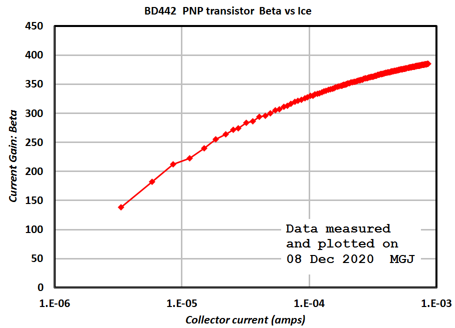
It occurred to me that the LockyZ curve tracer can save its measurement results to a .csv text file. And then I can slurp the data into Microsoft Excel, where I can make a plot having semilog axes. So I tried that with a high-beta PNP transistor, running it at the lowest collector currents I could manage. Results are below.
Here is a transistor whose beta falls as Ice falls.
The Excel spreadsheet is attached, inside a .zip archive, because the Forum software doesn't allow attachments of type .xls, but DOES allow attachments of type .zip.
_
Here is a transistor whose beta falls as Ice falls.
The Excel spreadsheet is attached, inside a .zip archive, because the Forum software doesn't allow attachments of type .xls, but DOES allow attachments of type .zip.
_
Attachments

It is not really surprising to see a (moderate) beta drop in the µA range for a power transistor intended to operate at the ampere level.
For a ballast transistor, it is certainly not a problem, and if a transistor has to be added in a darlington configuration, to increase the current capacity whilst keeping the base current low, that additional transistor will operate at a commensurately low Ic level, meaning a signal or driver type will be suitable.
These transistors will exhibit a drop at an Ic one or two orders of magnitude lower, which means this is not going to be a problem.
Another question is what is to be gained with a darlington? Lower input current, for sure, performance? It is less certain.
Circuits depending on the transconductance rather than current gain are going to be degraded instead.
Here is an illustration, with a plain-vanilla common emitter amplifier.
The ref output is a single transistor (the input transistor is disabled by shorting B-E), and out is the darlington output: there is a ~10dB drop in transconductance and thus voltage gain with the darlington.
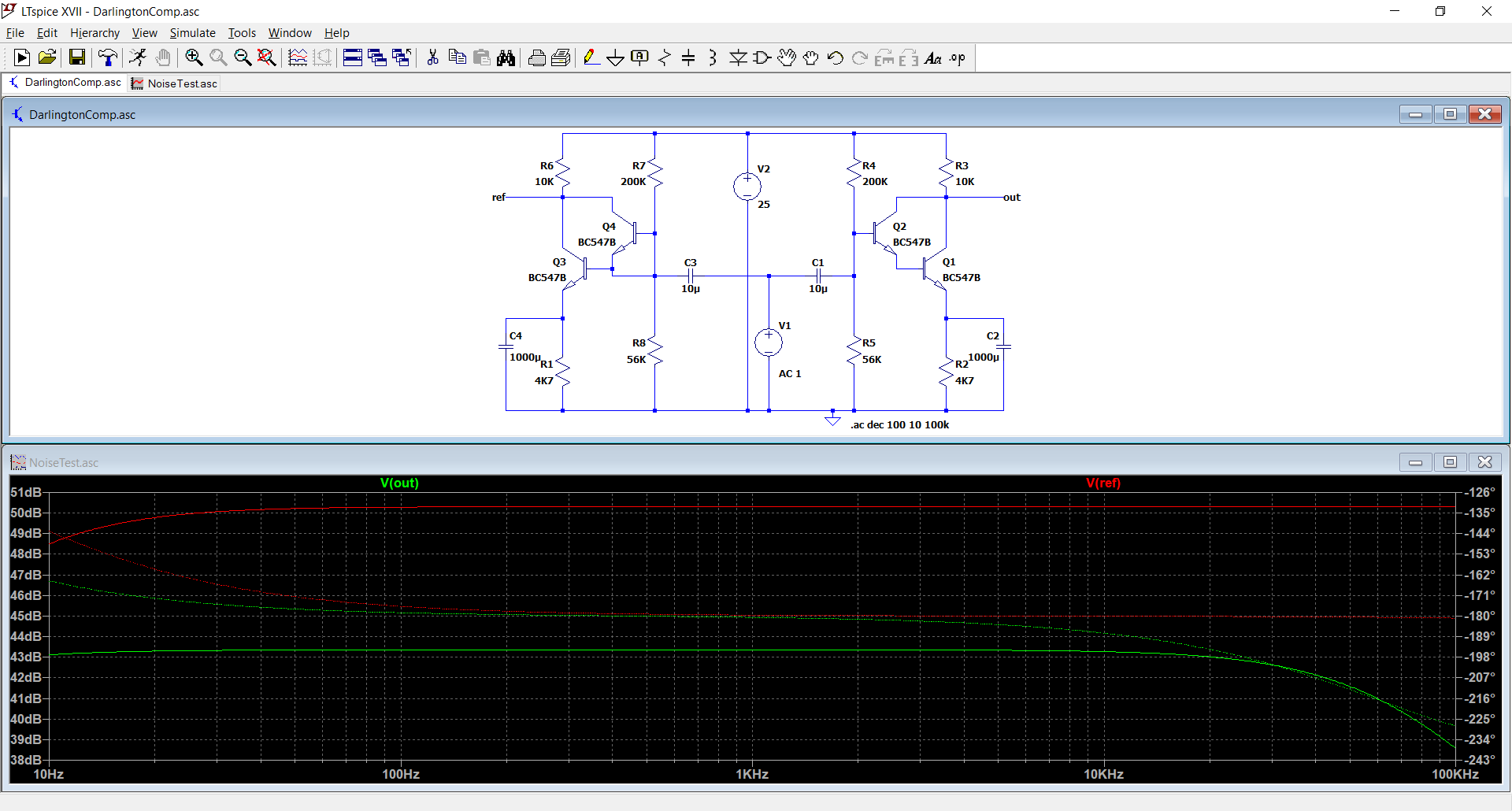
Of course, the input impedance could be higher, but in this case this feature isn't used.
The noise would also be increased, but for a ballast, this doesn't really matter.
Things would be different for the error amplifier, but converting it to a darlington would make little sense anyway
For a ballast transistor, it is certainly not a problem, and if a transistor has to be added in a darlington configuration, to increase the current capacity whilst keeping the base current low, that additional transistor will operate at a commensurately low Ic level, meaning a signal or driver type will be suitable.
These transistors will exhibit a drop at an Ic one or two orders of magnitude lower, which means this is not going to be a problem.
Another question is what is to be gained with a darlington? Lower input current, for sure, performance? It is less certain.
Circuits depending on the transconductance rather than current gain are going to be degraded instead.
Here is an illustration, with a plain-vanilla common emitter amplifier.
The ref output is a single transistor (the input transistor is disabled by shorting B-E), and out is the darlington output: there is a ~10dB drop in transconductance and thus voltage gain with the darlington.
Of course, the input impedance could be higher, but in this case this feature isn't used.
The noise would also be increased, but for a ballast, this doesn't really matter.
Things would be different for the error amplifier, but converting it to a darlington would make little sense anyway
Attachments
Nexperia BC847 transistors have far less hFE drop at low currents than I remember of their predecessor Philips BC547:
https://assets.nexperia.com/documents/data-sheet/BC847_SER.pdf
Improved annealing or so?
Philips BC550B, August 1987 datasheet:
hFE typ. 150 at 10 uA, 290 at 2 mA
Nexperia BC850B, January 2004 datasheet:
hFE typ. 240 at 10 uA, 290 at 2 mA
Nexperia BC847B, October 2019 datasheet:
hFE typ. 280 at 10 uA, 290 at 2 mA
Last edited:
- Home
- Design & Build
- Parts
- Search for BGTs with high Beta at low current