I don't know why I didn't think of this earlier, but...
Another way to reduce the sensitivity of the amp is to remove the cathode bypass capacitor for the 12AT7. That's the 220uF 50V cap that's in parallel with the 680 ohm resistor in your last schematic. Just leave that cap out and try it that way. It won't change the bias on the 12AT7, but it will reduce its gain, increase its output resistance (should not be an issue in this circuit), reduce PSRR of the 12AT7 (power supply ripple may be a bit more of a problem, or it might be under control enough that it's not a problem).
Another thing I just thought of....
The input of your amp is direct coupled. The amp will respond to signals all the way down to DC (0 Hz). In a NFB amp (like this one), that means the 12AT7 will try to boost low frequencies seen at the input when it gets the feedback signal coming from the output. If there are large low frequency signals/pulses like record warps or resonances from footfalls or a catridge/tonearm resonance that's too low (high compliance cartridge in heavy tonearm) then those pulses can cause the amp to overload on inaudible signals.
The solution is to put a capacitor on the input of the amp, go block frequencies that are below audibility. Try a 0.22uF cap in series before the input to the volume control (between where it says "INPUT" and the input lug on the 100k pot on the schematic).
0.22uF in series with 100k ohms shunt = -3dB at 7.2Hz
-or-
0.15uF in series with 100k ohms shunt = -3dB at 10.6Hz
IF (I don't know for sure, but IF) your 834P preamp is sending big low frequency pulses down the line, that could explain why some amps distort mysteriously when driven by that preamp, but others seem to work fine. It could be that some of the amps you've tried have DC-coupled inputs and overload on the low freq pulses, while others are AC-coupled (CR high pass filter on the input) and reject those low frequency pulses.
Could be. I think perhaps worth a try.
-
> remove the cathode bypass capacitor for the 12AT7
At first blush, that makes almost no difference. It is inside the global NFB loop.
In this case it makes slight difference, because the forward gain is about 40*0.5= 20 and the NFB fraction is 1/21, so there actually is not much NFB. Gain may drop several dB. Not enough to run wide-open with the neighbors at home.
Gain control used to be the #1 skill of the audio technician. But like mastery of the buggy-whip, that skill is lost. We now must accept whatever odd combination of gains our random bargain-buying has dragged home.
I did suggest trying more NFB to decrease the gain, but that didn't get much attention.
https://www.diyaudio.com/forums/tub...-dialing-12at7-driver-bias-3.html#post6699012
As you know, if you start adding a lot of NFB, stability issues start to become important. I don't think there's a way to look at leading edges of square waves in this particular situation. And maybe that's OK too.
If the problem is that the amp is too sensitive and clips with much less than 1V input signal, you can make the amp less sensitive, lower its distortion, and decrease its output impedance by reducing the value of the 2k ohm negative feedback resistor (from the output transformer's 8 ohm tap to the top of the 100 ohm resistor in the 12AT7 cathode circuit). Can you clip a resistor in parallel to that 2k ohm resistor? Perhaps start with 6.8k ohms in parallel (total 1.55k), see how that works. You could even go as low as 3.3k in parallel with 2k (total 1.2k).
https://www.diyaudio.com/forums/tub...-dialing-12at7-driver-bias-3.html#post6699012
As you know, if you start adding a lot of NFB, stability issues start to become important. I don't think there's a way to look at leading edges of square waves in this particular situation. And maybe that's OK too.
Last edited:
Since this is a simple SE amp, it would also be possible to run 'local' NFB from the plate of the output tube to the cathode of the input tube.
It would also be possible to employ cathode feedback around the output tube, as shown in the Tubelab Simple SE design.
Schematic | Tubelab
It would also be possible to employ cathode feedback around the output tube, as shown in the Tubelab Simple SE design.
Schematic | Tubelab
I merely seek to learn the wierding way, looks like I'm in the right place. Gonna try to remove that cathode bypass cap tmrw, see what I get. If that's a bust, I'll look at increasing the anode resistor to 100k, see what happens.
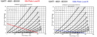
It's those load lines again...
I've attached two load lines for a 12AT7 with a B+ of 400V.
The first one shows the 12AT7 with a 33k ohm plate load resistor.
The second one shows the 12AT7 with a 100k ohm plate load resistor.
Notice how the 33k load line is more vertical. That means the voltage swings less (horizontally) as the input signal is applied, which means lower gain.
Notice how the 100k load line is less vertical (more horizontal). That means the voltage swings more (horizontally) as the input signal is applied, which means higher gain.
The more vertical the load line, the lower the gain.
The less vertical (more horizontal) the load line, the higher the gain.
To get the very most voltage gain possible you can use a constant-current source as the plate load, which will make a completely horizontal load line (the same plate current at almost all plate voltages).
--
Attachments
Last edited:

THIS is what I was waiting to hear. I had a feeling I needed to change the Plate resistor, now I know why!
I think 47k for the 12AT7 plate load resistor is fine.
I think what you want to change is the NFB resistor, to reduce the gain of this amplifier (and lower its distortion, and increase its 'damping factor').
You may also want to put a DC blocking capacitor at the amp's input.
I think what you want to change is the NFB resistor, to reduce the gain of this amplifier (and lower its distortion, and increase its 'damping factor').
You may also want to put a DC blocking capacitor at the amp's input.
remember that for the driver tube, you need plate voltage to drive the output grid to near zero volts, and you need plate current to slay the miller caps of the output tubes...
THIS is what I was waiting to hear. I had a feeling I needed to change the Plate resistor, now I know why!
the plate load resistor determines your voltage gain...which will never exceed 1/2 of the triode mu...
What is the input capacitance (Miller capacitance) of a triode-wired 6L6GC? Pretty low. Like 60pF, maybe. The input capacitance will be lower for UL configuration. 3mA plate current from the driver should do it. More would be nice, true. Not mandatory though.
A good rule of thumb to follow is for the driver tube to be able to swing twice the peak voltage (+6dB) required to drive the output tube to clipping (grid current and/or cutoff).
If the grid bias on your 6L6GC is -30V, then -ideally- you want the driver stage to be able to swing 60V peak (or 120V peak to peak -- same thing, different way of saying it).
the plate load resistor determines your voltage gain...which will never exceed 1/2 of the triode mu...
That's not true.
I'd say you will never be able to exceed about 75% the data sheet rated mu.
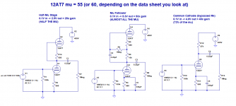
There is a thing MerlinB calls the 'half-mu stage', which is basically a quasi-SRPP with the output signal taken off the plate of the bottom triode (instead of from the cathode of the top triode). That gives you... half the mu.
The first stage of Broskie's Aikido line stage is a half-mu stage.
--
That's not true.
I'd say you will never be able to exceed about 75% the data sheet rated mu.
There is a thing MerlinB calls the 'half-mu stage', which is basically a quasi-SRPP with the output signal taken off the plate of the bottom triode (instead of from the cathode of the top triode). That gives you... half the mu.
The first stage of Broskie's Aikido line stage is a half-mu stage.
--
he is using a plate load resistor, you are talking about mu followers, i merely posted the consequence of the plate load resistor based on what the OP said...
what is with this design? does in have enough open loop gain?, in triode mode, is it stable with global feedback?
sheeit, I'm just a tube noob who tried to copy a DIY design to make my own. Building the same amp with 80v more on the b+ made an amp with a very temperamental input, and I wanna know why. but y'all are giving me loads of good info.
i also made an all pentode single ended tube amp using the 12gt5 and the 6bn11, i made provisions for a global feedback, but then i found out that even without global feedback the amp sounded gloriouly...
- Home
- Amplifiers
- Tubes / Valves
- SE 6L6GC Amp - dialing in the 12AT7 driver Bias