I took this from the speaker out of the Mofo attached to the Scourge units in question. It's definitely HF garble wrapped in a 120Hz sleeve at about 1v peak to peak..
Noise gets noticeably worse when the DAC (Schiit entry level unit) is attached even if it's not powered up. However, the noise is present with no input attachments as well with inputs grounded (inputs ground by the pot being turned down). I also attached a small set of amplified speakers and heard the same buzz to rule out the Mofos which appear to function just fine with other input sources. The area isn't inherently noisy as far as I'm aware. Multiple preamp (ACP+, BOZ, etc) all function perfectly in the same spot.
Still feeling I should build up a more traditional setup (supply/regulator/grounded aluminu. Chassis, etc) Would be a bummer if that route got The same results.
The mystery continues
Attachments

Last edited:
I'll put a resistor across the Scourge D+/D- and scope across the resistor, with various items attached both source and output.
Solved....
Ground strap between Mofo and scourge boards....silence!
Even with laptop supply instead of batteries.
I ended up jumpering D-- to V- and seemingly problem solved. Mofo and front end then reference ground through RCA connection.
Grrr....! Now time to put things back together that didn't need to be tore apart in the process.I
Thank You for the look ThompsonTech.
Well, I have all the resisters installed on the Dread... I can't say I ever soldered in 100 of them on an FE before. lol. I also have the few diodes in too. In past years I would have it all done by now, but not so much these days. All the Rs were there plus a couple 3.3R resistors...? Anyway, on to the rest. 🙂
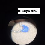
With the Dread kit I got a C26 cap marked 4R7 is this correct? SHouldn't that be marked 4p7? I don't have anything to measure that reliably. The schematic calls for a 4.7pF NP0/C0G ceramic in that position.
JT
JT
Last edited:


Thanks Mark, the pictures and note were, most helpful.
I did look up the part number, from the BOM and the confusion was over the R vs P marking. I did find a cheap LC meter and it tested about 4.6pF, so all is well.
JT
I did look up the part number, from the BOM and the confusion was over the R vs P marking. I did find a cheap LC meter and it tested about 4.6pF, so all is well.
JT
![20230324_145436[1].jpg](/community/data/attachments/1065/1065242-832eba5d4101f4bdd507b509323f3f72.jpg?hash=gy66XUEB9L)

Purchased a Bulwark kit and began assembly - intending to use a a preamp for now. Made the assumption given transformer (edcor) output provide opposite phase outputs, that could use balanced output to to drive F4 monoblocks. This correct? Attaching pic, may have t
 he pinout of xlr messed up looking depending on perspective... but for different point. Making guess that xlr ground at the pre/bulwark side just connect to power supply ground and the 47k input resistor at the F4 for each keep the D+ and D- 1/2 diff from ground.
Also, in the kit there were 4 of the resistors that look to be the feedback resistor, R22. What is the value of that resistor given the meter reading bounce around like would for 1 ohm or less value - well know I can just look up resistor color codes but perhaps edumacational value about that value.
Also, in the kit there were 4 of the resistors that look to be the feedback resistor, R22. What is the value of that resistor given the meter reading bounce around like would for 1 ohm or less value - well know I can just look up resistor color codes but perhaps edumacational value about that value.

"For builders of Marauder and Bulwark: don't forget to read post #55 of this thread, for instructions how to set the trimmer potentiometer in the DC-to-DC converter (page JBOOST of the schematics)."
Marauder and Dreadnought Mark. Mistype above.
Something I might have called to your attention privately....
JT
Marauder and Dreadnought Mark. Mistype above.
Something I might have called to your attention privately....
JT
Last edited:

Ooooh, very nice Dreadnought build, @thompsontechs !! Great job soldering and spectacular job with flux removal // clean up // making ready for glamour photos. Good on ya.
It appears you prefer to avoid stuffing and soldering the resistors & diodes in the suggested vertical "stand up straight" orientation. Which is perfectly fine, as long as you're able to clip your scope probe to component lead(s) during debugging.
It appears you prefer to avoid stuffing and soldering the resistors & diodes in the suggested vertical "stand up straight" orientation. Which is perfectly fine, as long as you're able to clip your scope probe to component lead(s) during debugging.
I like them low to avoid possible shorts, nothing wrong with vertical, as it makes sense when you have this many parts in such a small space.
I will could use the debug space now as I have something hosed on them both.
Rail 36v pos
Pin7 50kHz at about 30v
Boosted output as measured at L1 is 58v
Input sine 1kHz at 1.2vpp
Output 1.5vpp (Hmmm)
If I take the input up more I get a nasty clip on the pos wave. Basically, I'm not getting any amplification. Both light work as does the invert, but I have something going on somewhere, probably something simple, no smoke nothing gets hot. I built them both at one, so whatever I screwed up it's the same on both boards.
So far all resistors look and measure proper. Verified all the semis are in the right places. The chips are correct as far as I can tell. Diodes look good. I mulling now....
Last edited:
I'd start by making sure the power supply circuits are working correctly. Measure nodes 1 and 4 at DC with voltmeter, they ought to be > 33V DC .
Measure node 2, it ought to be more than 60 volts.
Measure node 3, it ought to be at least a half volt higher than node 2.
Put a scope on node 5, it ought to be a 50 kHz square wave, slightly lower amplitude (1-2V less) than U6 pin 7.
Happy hunting!
Measure node 2, it ought to be more than 60 volts.
Measure node 3, it ought to be at least a half volt higher than node 2.
Put a scope on node 5, it ought to be a 50 kHz square wave, slightly lower amplitude (1-2V less) than U6 pin 7.
Happy hunting!
Attachments

- Home
- Amplifiers
- Pass Labs
- Scourge, Bulwark, Marauder, Dreadnought "front end" cards for DIY VFET amp