Get this sort of readings out of the driver tubes in my 300B push pull amp. The driver tubes are ECC99. The amp has been working perfectly for many years but one day the amp got distorted and a bit low in volume. When measuring all voltage they seem to be ok. Tried a new set of input and driver tubes but it didn't help so clearly I`m overseeing what should be the obvious.


This looks a lot like interstage capacitance leakage driving the following stage into grid current. Check/replace the coupling caps.
Cheers
Ian
Cheers
Ian
Switch on power and the scope img. stays like this for ca 30sec.

And then slowly turns into this.

And then slowly turns into this.
These img. is taken from pin 2 on the ECC99 tube. When I take out one of the two ECC99 the sinewave is perfect.
330n coupling caps are ok.
I have 12BH7As (20mA, 300mA @ 12.6V heater) and ECC99s (60mA, 400mA @ 12.6V heater) in a design. They are not a direct swap without a little playing for the heaters and idle.
I note that the schematic indicates paired 12BH7As and not EC99s. I have a feeling that the power rail supply is being dragged down, possibly the power transformer heater winding attempting to supply too much current?
Removing one of the ECC99s results in a good sine wave suggests the rail/heater being pulled down.
Yes, that was my thought too. But its the same when I switch back to 12BH7. I`ve used the ECC99 for some time now. But you have a point there.I have 12BH7As (20mA, 300mA @ 12.6V heater) and ECC99s (60mA, 400mA @ 12.6V heater) in a design.
I note that the schematic indicates paired 12BH7As and not EC99s. I have a feeling that the power rail supply is being dragged down, possibly the power transformer heater winding attempting to supply too much current?
Well given two BH7As will be 40mA max on the B+ and 600mA on 12.6V vs a pair of ECC99s being 120mA max and 800mA on the 12.6V.. I would say that's probably your problem.
EDIT: I see you've just responded. Hmm have you checked the power supply windings in case running the ECC99s have caused a short?
EDIT: I see you've just responded. Hmm have you checked the power supply windings in case running the ECC99s have caused a short?
Powersupply is OK. So in case the ECC99 is drawing too much current I should go back to two 12BH7. Or just one ECC99?Well given two BH7As will be 40mA max on the B+ and 600mA on 12.6V vs a pair of ECC99s being 120mA max and 800mA on the 12.6V.. I would say that's probably your problem.
EDIT: I see you've just responded. Hmm have you checked the power supply windings in case running the ECC99s have caused a short?
As the tubes are direct coupled the operating points are critical so they don't "fight" each other . Exactly such distortion you can see in that case . If you say it worked ok , maybe something has drifted overtime , you should check all parts . Even if B+ is not as expected , the direct coupled combination can distort like this .
You can't swap tubes so easily in this case ... even the same types could make the combination to be unbalanced , especially if the design wasn't that good in the first place .
You can't swap tubes so easily in this case ... even the same types could make the combination to be unbalanced , especially if the design wasn't that good in the first place .
Last edited:
I have all the components on a pcb and luckily I ordered 5 of them so I simply stuffed another board with new ones. Except the 330nF coupling caps. Took me 30 minutes. Not so good with understanding all about tubes but boy do I know how to swing a solder iron. 😈As the tubes are direct coupled the operating points are critical so they don't "fight" each other . Exactly such distortion you can see in that case . If you say it worked ok , maybe something has drifted overtime , you should check all parts . Even if B+ is not as expected , the direct coupled combination can distort like this .
Pin 2 is the grid, the input of the stage, what do you see at the anodes ? The voltages in the schematic (211V) can't be right, shoud be over 300V.These img. is taken from pin 2 on the ECC99 tube.
One or the other the same result ? Try without feedback, the deformation can come from the feedbach trying to correct a malfuntion in the output stage.When I take out one of the two ECC99 the sinewave is perfect.
Mona
Attachments
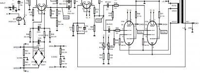
About the schematic see (post #4).
My guess is that Mona wrote that the anode voltage of the 12BH7's can't be right because of the absurd low cathode to anode voltage, namely 37 V, at an absurd bias, namely -7 V.
But surprisingly the currents through the anode resistors R1 (6.4 mA) and R15 (6.4 mA) equal the currents through the cathode resistors R3 (6.4 mA) and R5 (6.4 mA) when using the values in the schematic. The voltages around the EF86 are in line with the datasheets so the grid voltage of 176 V indicated for the 12BH7's can't be far off.
What are the odds on something like that?
211V with both tubes in place. 311 with one tube in place. So the powersupply surely can't be enough for two of them, I think.Pin 2 is the grid, the input of the stage, what do you see at the anodes ? The voltages in the schematic (211V) can't be right, shoud be over 300V.
One or the other the same result ? Try without feedback, the deformation can come from the feedbach trying to correct a malfuntion in the output stage.
Mona
All the voltage in #4 is with two ECC99 in place. Not 12BH7 as it says.About the schematic see (post #4).
My guess is that Mona wrote that the anode voltage of the 12BH7's can't be right because of the absurd low cathode to anode voltage, namely 37 V, at an absurd bias, namely -7 V.
But surprisingly the currents through the anode resistors R1 (6.4 mA) and R15 (6.4 mA) equal the currents through the cathode resistors R3 (6.4 mA) and R5 (6.4 mA) when using the values in the schematic. The voltages around the EF86 are in line with the datasheets so the grid voltage of 176 V indicated for the 12BH7's can't be far off.
What are the odds on something like that?
That doesn't matter much. The voltages indicated can't be right, either with 12BH7 or with ECC99. With your voltages, one triode section would pass 3.2 mA, with -7 V bias and only 37 V between cathode and anode. Look at the curves in the datasheets. It's impossible.
- Home
- Amplifiers
- Tubes / Valves
- Scope readings.