Indicating that there is something very wrong in the amp?That doesn't matter much. The voltages indicated can't be right, either with 12BH7 or with ECC99. With your voltages, one triode section would pass 3.2 mA, with -7 V bias and only 37 V between cathode and anode. Look at the curves in the datasheets. It's impossible.
Ok. I will take new measurements and post them here.It indicates that the voltages in your schematic in your post #4 are impossible.
That doesn't matter much. The voltages indicated can't be right, either with 12BH7 or with ECC99. With your voltages, one triode section would pass 3.2 mA, with -7 V bias and only 37 V between cathode and anode. Look at the curves in the datasheets. It's impossible.
Agreed neither tube will like running in that voltage range.
Yes, but I must clearify. With 12BH7 for many many years. With ECC99 for about a year. It is a set of monoblocks and the other one is still running as it should. These amps have been workink like this since 1993 with 12BH7.TS wrote that the amplifier has been working perfectly for many years...
LA Audio. My version does bot have the fourth tube as this version. I think this was one with 12AT7 on the input with 12BH7.

That is what you always says......... isnt it?I feel something pulling my leg again, so I'm out of this thread.
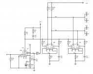
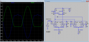
Just LTSPiced this.
According to LTSpice with ecc99s all connected with the second pair grid not connected (as per your design) you're getting about 3.9mA across the Ra resistors. What you are also getting with 1mili-ohm (ie 1m rather than 1M) is about 20mA grid flow.
I've put in a voltage bias for the grids at your measured 161.5V and also put in a 100Vpp 1KHz sine - that gives about 8Vpp which is ok for the ecc99 grid.
With the second pair grids connected you get about 7mA across each Ra and about 8Vpp output.. (I've not modelled the very small coupling caps on the output).
What's your NFB connected to? It seems to connect direct to the cathode of the front end.


The issue is you have a grand total of 33V across the ecc99. Which isn't going to result in a real world nice sound. The cathode sits at 162V and the anode is sitting at 195V. When you really want about 150V across them. They have 3.6mA idle.. which is really bad for both the 12BH7A and the ecc99 which for example an idle point would typically be 9-13mA and 24mA respectively. You're not hitting the max of 200Vdc peak above the heater.
According to LTSpice with ecc99s all connected with the second pair grid not connected (as per your design) you're getting about 3.9mA across the Ra resistors. What you are also getting with 1mili-ohm (ie 1m rather than 1M) is about 20mA grid flow.
I've put in a voltage bias for the grids at your measured 161.5V and also put in a 100Vpp 1KHz sine - that gives about 8Vpp which is ok for the ecc99 grid.
With the second pair grids connected you get about 7mA across each Ra and about 8Vpp output.. (I've not modelled the very small coupling caps on the output).
What's your NFB connected to? It seems to connect direct to the cathode of the front end.
The issue is you have a grand total of 33V across the ecc99. Which isn't going to result in a real world nice sound. The cathode sits at 162V and the anode is sitting at 195V. When you really want about 150V across them. They have 3.6mA idle.. which is really bad for both the 12BH7A and the ecc99 which for example an idle point would typically be 9-13mA and 24mA respectively. You're not hitting the max of 200Vdc peak above the heater.
Last edited:
Thanks. This is the kind of stuff needed for a diy`er. Education. Not to hear that someone is pulling anybodys leg, an get sour.......Just LTSPiced this.
According to LTSpice with ecc99s all connected with the second pair grid not connected (as per your design) you're getting about 3.9mA across the Ra resistors. What you are also getting with 1mili-ohm (ie 1m rather than 1M) is about 20mA grid flow.
I've put in a voltage bias for the grids at your measured 161.5V and also put in a 100Vpp 1KHz sine - that gives about 8Vpp which is ok for the ecc99 grid.
With the second pair grids connected you get about 7mA across each Ra and about 8Vpp output.. (I've not modelled the very small coupling caps on the output).
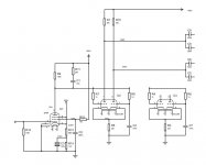
What's your NFB connected to? It seems to connect direct to the cathode of the front end.View attachment 1048446
View attachment 1048447
The issue is you have a grand total of 33V across the ecc99. Which isn't going to result in a real world nice sound. The cathode sits at 162V and the anode is sitting at 195V. When you really want about 150V across them. They have 3.6mA idle.. which is really bad for both the 12BH7A and the ecc99 which for example an idle point would typically be 9-13mA and 24mA respectively. You're not hitting the max of 200Vdc peak above the heater.
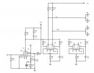
The NFB is just a 47K connected to the front end. Any suggestion what would be the best solution to solve the "problem"?Just LTSPiced this.
According to LTSpice with ecc99s all connected with the second pair grid not connected (as per your design) you're getting about 3.9mA across the Ra resistors. What you are also getting with 1mili-ohm (ie 1m rather than 1M) is about 20mA grid flow.
I've put in a voltage bias for the grids at your measured 161.5V and also put in a 100Vpp 1KHz sine - that gives about 8Vpp which is ok for the ecc99 grid.
With the second pair grids connected you get about 7mA across each Ra and about 8Vpp output.. (I've not modelled the very small coupling caps on the output).
What's your NFB connected to? It seems to connect direct to the cathode of the front end.View attachment 1048446
View attachment 1048447
The issue is you have a grand total of 33V across the ecc99. Which isn't going to result in a real world nice sound. The cathode sits at 162V and the anode is sitting at 195V. When you really want about 150V across them. They have 3.6mA idle.. which is really bad for both the 12BH7A and the ecc99 which for example an idle point would typically be 9-13mA and 24mA respectively. You're not hitting the max of 200Vdc peak above the heater.
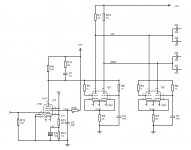
The NFB is just a 47K connected to the front end. Any suggestion what would be the best solution to solve the "problem"?
whAt is the measured Vpp (and dc) on the grids of the ecc99s. It coild be those 1m resistors which allow the vpp to be pulled down.
Im concerned the ecc99 grids may be pulling cirrent, dropping voltage.
How would you know? 😉330n coupling caps are ok.
Please post the full schematic.
What is being coupled to?
- Home
- Amplifiers
- Tubes / Valves
- Scope readings.