Output resistance is proportional to hfe1 x hfe2, so it doesn't matter which one is which and you certainly don't need to match transistors.
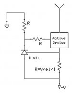
I'm doing a little design with a CCS on a LTP, and I was wondering, what is considered "good" for impedance of a CCS? I've ordered some parts and am gonna do some experimenting. I was looking into something like this, with the possibility of a FET or BJT as the active device. The FET I've ordered has an output capacitance Cds of 55pF (IRFBF20), which is about -j130kohms at 20KHz. If it doesn't work out with this, I will cascode with a proven design. The design current is 28mA.
So back to the question, what is acceptable for CCS capacitance and/or impedance? I don't have a spice program with tubes so it's hard for me to do any simulations.
thanks,
Micah
So back to the question, what is acceptable for CCS capacitance and/or impedance? I don't have a spice program with tubes so it's hard for me to do any simulations.
thanks,
Micah
How long is a piece of string?
It all depends on application. Suppose you wanted an active anode load for an ECC83. You'd want at least 50 x ra = 4M. What about capacitance? Well, if you were only concerned with audio, you might feel that a shunt capacitance with a reactance that equalled the 4Mresistance at 100kHz would be required. C = 1/2pifX = 0.4pF. Quite small.
Conversely, you might need a CCS as an active load for a 6C45, in which case, you could scale the resistance and capacitance by a factor of 50 and say that 80k would be fine and 20pF would be fine.
I hope you can see that what you have to do is to determine the effect of an imperfect CCS on the circuit and decide what is acceptable.
Um.
The TL431 has been around for a long while. That says two things. Its DC reference is noisy and the op-amp is similar to a 741 (not much gain). You can do much better with two transistors. Really, you can.
The TL431 has been around for a long while. That says two things. Its DC reference is noisy and the op-amp is similar to a 741 (not much gain). You can do much better with two transistors. Really, you can.
Ready
Ok, I made a double one with on board rectifier and filter cap. I went through 10s of red, green, & yellow LEDS. Reds are 1.43V-1.53V forward voltage drop and vary the most. Greens are 1.74V-1.75V and vary very little, ambers are 1.70V and vary very very little. I chose 2 identical amber ones. I was lucky to find a couple of strong hfe BC550Cs in my stash so they keep hfe*hfe product high enough in combination with the mild hfe 240 123APs I had (thanks EC8010).
This little board is going to be tested soon, draining a 12AT7 Schmidt phase splitter in a finished amp of mine. That amp already measures a low 1.5% AC Balance offset, so it is going to be a passive VS active current drain comparison mainly. I have to clear space and rewire in there etc. So I will let you know of the sonic results in due time.
Attachments

You are running a very low current through that LED (only about 0.1 mA). It is usually recommended to use a few mA to improve voltage stability, and reduce noise from the LED. This would require the resistors to be reduced from 27K to around 1K.
SveinB.
SveinB.
Thanks! The lower I go with the resistors, the sim shows degraded AC balance on the splitter outputs. But I will parallel the 27k resistors with 2k2 ones so I will jump from 0.15mA to 2mA through the LED. I hope this will prevent any noise issues to a good degree.
Or, you could put another resistor from ground to the top of the LED to provide it additional current, and leave the two 27K resistors alone.
Listened to it.
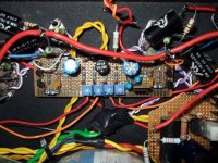
I made a new combo mini board with 2 cascode BJT CCSs along with a fix bias control circuit to implement in my freshly reworked KT88 amp. Svein_B recently had a thread about 100Hz IMD intrusion in the voltage reference, concluding that it takes regulation on B+ and -CCS supply for things to be optimal. So I used a Giaime Ugliano Mosfet Maida for the first stages and I regulated at -30V with a LM337T for the CCS tail, tapping off the fix bias PSU. LED works at 5mA. The CCS drains a 12AT7 pair at 3mA each, @ 340V B+.
The sonic conclusions are: No loss of liquidity compared to the resistor tail. Noticeably better slam in the bass to mid bass, more tactile and revealing mid - high. More organized depth and hall cues. In general a surely precise but not artificial sound. No added harshness, enhanced sense of tranquility, better control during transients.
Attachments
Re: Listened to it.
Gee man, I’m jealous. Need to redo my 6550
🙄
salas said:
No loss of liquidity compared to the resistor tail. Noticeably better slam in the bass to mid bass, more tactile and revealing mid - high. More organized depth and hall cues. In general a surely precise but not artificial sound. No added harshness, enhanced sense of tranquility, better control during transients.
Gee man, I’m jealous. Need to redo my 6550
🙄
- Status
- Not open for further replies.
- Home
- Amplifiers
- Tubes / Valves
- Schmitt & CCS