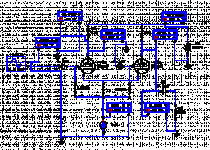
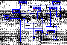
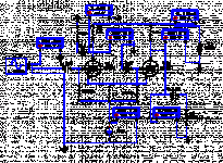
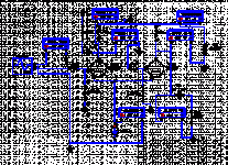
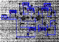
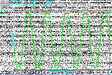
Thats one way to correct them when they have an inadequate tail... Its sometimes deliberate practice when a resistive tail is used.
Funny is that they needed a little imbalance to perform better even with the CCS! I have simulated higher mu tubes too. My early conclusions are: 1. Higher μ tubes AC balance closer with just a tail resistor. Near to CCS. 2. For minimum complexity CCS, and DC levels that not squeeze the tubes working envelope, must have compatible rest of circuit conditions so to DC couple the input. 3. If it must be AC input coupling its getting complex to CCS the Schmidt (or Schmitt?), maybe better off with the 12AT7/6SL7 class for good AC balance and PP output stage drive, with just a resistor tail.
Salas,
You have only 6 volts from plate to cathode, and one plate has an additional 300K load that the other doesn't have. The plate loads need to be the same. Place a 300K load with coupling cap on the other plate too, and try reducing the CCS current to give more voltage across the tube. Then you'll have balance and proper operation.
You have only 6 volts from plate to cathode, and one plate has an additional 300K load that the other doesn't have. The plate loads need to be the same. Place a 300K load with coupling cap on the other plate too, and try reducing the CCS current to give more voltage across the tube. Then you'll have balance and proper operation.
Try grounding the bottoms of the two grid leak resistors. Replace the 1K cathode resistor with a wire, and set CCS current for 8mA, just for now.
Hi Salas,
Very curious behaviour indeed !
As Brian stated, the anodes are only 6V higher than the voltage accross the current source . . . wich is not the cathodes ! !
In fact you sould have 6V accross the 1K cathode resistor since there are 6mA flowing into.
If so, it remains 0 V from plates to cathodes, may be a approximation in the SPICE model for the triodes ? ?
The problem is caused by the return of the grid resistors that should be on the negative side of the CCS (the 1K res being superfluous).
Doing that, the voltage accross the CCS set itself at exactly the Vgk the tubes need to pass exactly 6mA, whatever the plate voltage could be.
In this case, with the 12AU7, 47K in plates and 300V B+, Vgk can be estimated in the 5 to 7V range.
If your CCS still works with such voltage then you win.
If not, you need either :
-an auxiliary negative supply to return the CCS to (while grids still referenced to ground).
-reference the grid at some fixed positive voltage wich does not depend of the CCS.
Yves.
Brian Beck said:Try grounding the bottoms of the two grid leak resistors. Replace the 1K cathode resistor with a wire, and set CCS current for 8mA, just for now.
Yes! 8mA is the working point.
Attachments
That looks much better. However (you knew there had to be a "however"), although you have 6V on your cathode, and that's enough to power a cascode CCS, you are using this stage as a phase splitter, and that means you see half your input signal on the cathodes. Once you apply a healthy signal, you may not have enough voltage left to allow a cascode CCS to work properly. The solution is easy enough; you just need a negative supply of about -12V for the CCS. As you don't like the word "force", I'll just say that with a -12V supply for the CCS, your phase splitter will be "allowed" to work perfectly with matched anode load resistors.
Yes - Or... you can reference the bottoms of the grid leaks to say, +12V, fashioned from a voltage divider off B+, suitably filtered to ground with a cap. This avoids the need for an additional supply. If you stick with a B+ of 360 v (perhaps a bit high if you ask me), you could use a 680K upper resistor and a 24K lower resistor. Carbon comps would be fine here. Add a cap across the 24K and you're off to the races.
As they are, 11k referenced to ground, or 8mA CCS referenced to ground and grids also, non clip input signal ceilings are: Resistor 12VRMS (34VPk-Pk), CCS 14VRMS (40VPk-Pk).
Brian Beck said:Yes - Or... you can reference the bottoms of the grid leaks to say, +12V, fashioned from a voltage divider off B+, suitably filtered to ground with a cap. This avoids the need for an additional supply. If you stick with a B+ of 360 v (perhaps a bit high if you ask me), you could use a 680K upper resistor and a 24K lower resistor. Carbon comps would be fine here. Add a cap across the 24K and you're off to the races.
Unfortunately, biasing the CCS either with reference to negative or positive (see pic) did not rise the input margin before onset of clip on the outputs.
Attachments
salas said:Unfortunately, biasing the CCS either with reference to negative or positive (see pic) did not rise the input margin before onset of clip on the outputs.
That's easily explained by the increase in the grid voltage by about 12 v to give the CCS more breathing room, which reduced the plate-to-cathode voltage by the same amount, slightly reducing the tubes' headroom. Raise the B+ in the sim to 372 v to restore the lost headroom. Of course, all this is merely academic until you specify how much output swing you really need.
In circuits driving 6550s or KT88s in triode with 400V B+ and bias from 50-60mA 80-90VPk-Pk is needed. Add 20% headroom, 110VPk-Pk is ok. The 8 mA CCS'd 12AU7 360V B+ circuit gives 208VPk-Pk before clip. 6SN7 does 9% better in same circuit. Both resistor and CCS circuits show adequate swing. Its a pass.

Circuit about to test.
Hello all,
Here is the CCS CAD that I am about to put together on a small perforated board and test its sonic benefits over the classic resistor tailed splitter. This block is driven by a common cathode 12AY7 paralleled pair, and by its turn, drives a PP KT88 triode strapped pair with -40VDC fix bias on their grids. I have NPN BJTs that their HFE spans from 175 to 245 among the 4 of them. My question is, what is going to be more productive? Use the stronger ones for upper or low tier in the cascode? Also is it better to average their HFEs per pair, or just group the strong with the strong and the weak with the weak? In other words do I have to act capitalistic or socialistic?😎
Attachments
...been deeper into my part bin and found 2 matched BC550C Toshiba hfe 495, and 2 NTE 123AP hfe 220. I think that the stronger hfe must be the low tier BJT in the cascoded CCS. So BC550 down, 123AP up. Is that ok? I also have very many red, green and yellow leds to pick and match fwd volt. drop from. Is there a lower noise or temp comp preference between colors?
- Status
- Not open for further replies.
- Home
- Amplifiers
- Tubes / Valves
- Schmitt & CCS
