Audionewb,
Thanks for the parts list. Just completed my orders with digikey and mouser (had other stuff to get there as well). I plan on building this new output system, as well as replacing the RCAs in my system with 75 ohm BNC jacks and cabling (per the S/PDIF spec). Purportedly this should really help, since RCA's aren't a great connector for digital transmission systems from what I've read.
I've got a monarchy DIP on the way as well, so combining all this with my modded M-Audio SuperDAC 2496 should be interesting!
Next up for the CD-602 is a pair of linear supplies based on Tangent's "tread" PSU boards.
Mike
Yup, that's what I'm thinking as well. Evidently you can build a dual voltage PS (as in 12v/5v) with two of them and a dual-secondary transformer. Let us know, if you go that route, what resistor values and transformer you end up with. Be really cool to pull it off with an ultra-quiet toroidal job!motherone said:Next up for the CD-602 is a pair of linear supplies based on Tangent's "tread" PSU boards.
AudioNewb said:Yup, that's what I'm thinking as well. Evidently you can build a dual voltage PS (as in 12v/5v) with two of them and a dual-secondary transformer. Let us know, if you go that route, what resistor values and transformer you end up with. Be really cool to pull it off with an ultra-quiet toroidal job!
That's the plan. Gotta go find decent split bobbin core transformer for this. I might have some in the parts bin, but I need to look up their specs again 😀
AudioNewb said:
Great, thanks! On the resistors, Mouser doesn't stock ¼ watt 1% Vishay/Dales in 330 and 97 ohm right now. If 1/2 watt .1% is okay (an unneccesary upgrade?) I can stick with Vishays, or I'll have to switch to a different brand.
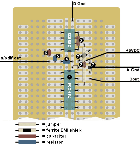
Here's the updated circuit. Getting a little crowded in the 'power section', hopefully its clear enough. Is this what you had in mind? Also, does polarity matter for the other two caps?
Just curious what software you are using to make the breadboard layouts?
Gcollier said:Just curious what software you are using to make the breadboard layouts?
Photoshop. Nothing automated about it...

AudioNewb said:
Photoshop. Nothing automated about it...
Thanks, I figured it was some kind of CAD software that I was unaware of...I guess not 🙁
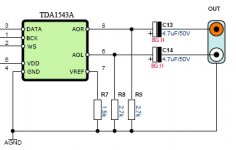
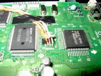
sivalleydiyer said:Finally, an internal view of where the dig lines were intercepted for the sony format to the TDA1543A. The two clock and data lines were taken from a resistor pack near the CXD2510. The "twisted pair" mates for the CAT5 wire were taken to ground found on the adjacent chip.
Power right now is provided by a small switching power supply, soon to be batteries when I find the time.
Works well so far!
I'd like to do the same. I intercepted the digital lines from pins 32, 34, and 35 from the CXD2510Q as well.
Can someone tell me which pins on the TDA1543A these lines connect to? Or the entire pin-out of the TDA1543A. I can't find any info on that chip.
I can't wait to get it playing. Thanks
Dave
Hi Dave,
This is the pinout I used for my TDA1543A from the Sony CDXQ10
CXD2510Q pIn 35 (BCK) to TDA1543a pin 1 (BCK)
CXD2510Q pIn 32 (LRCK) to TDA1543a pin 2 (WS)
CXD2510Q pIn 34 (DATA) to TDA1543a pin 3 (DATA)
CDR 6O2 Ground to TDA1543a pin 4 (GND)
The same pinout works for TDA1545, which I have also tried.
There is no separate data sheet for TDA1543A, only for 1543. However the only difference is that the 1543A accepts EIAJ and 1543 accepts I2S.
You should be able to download a data sheet here:
http://www.alldatasheet.com/datasheet-pdf/pdf/PHILIPS/TDA1543.html
Cheers, Joe Newbold
jnewbold said:Hi Dave,
This is the pinout I used for my TDA1543A from the Sony CDXQ10
CXD2510Q pIn 35 (BCK) to TDA1543a pin 1 (BCK)
CXD2510Q pIn 32 (LRCK) to TDA1543a pin 2 (WS)
CXD2510Q pIn 34 (DATA) to TDA1543a pin 3 (DATA)
CDR 6O2 Ground to TDA1543a pin 4 (GND)
The same pinout works for TDA1545, which I have also tried.
There is no separate data sheet for TDA1543A, only for 1543. However the only difference is that the 1543A accepts EIAJ and 1543 accepts I2S.
You should be able to download a data sheet here:
http://www.alldatasheet.com/datasheet-pdf/pdf/PHILIPS/TDA1543.html
Cheers, Joe Newbold
Is there a way this can be done easily with an 18 bit AD1865 DAC. I have and NEC 3XP+ transport that I would love to mod or add a nice DAC to, but my digital experience is very limited.
Is there a way this can be done easily with an 18 bit AD1865 DAC. I have and NEC 3XP+ transport that I would love to mod or add a nice DAC to, but my digital experience is very limited.
My digital experience is also limited, which is why I have stuck with TDA1543 and 1545, for the time being at least. The simplicity o these DACs, especially if you use TDA1543A and 1545 with EIAJ direct from the NEC CDR makes it difficult to get things really wrong and also allows you to eliminate the Crystal CS8412 receiver from the equation.
And they do sound very good indeed.
If you are set on the AD1865, you might try a search of this forum for information. For example the following URL has a discussion on using this chip.
http://www.diyaudio.com/forums/showthread.php?s=&threadid=48718&highlight="AD1865"
Okay, I tried tapping into the output from the CXD2510Q and running it directly to a TDA1543A. I can barely hear the CD play because there is so much noise in the signal. Here is a pic of the schematic I used for the 1543A. I used CAT5 cable to go from the CXD2510Q to the TDA1543A. Pin 35 to pin 1, pin 32 to pin 2 and pin 34 to pin 3. The TDA1543A is supplied with 8 volts.
Any idea why I might be getting this noise? I don't have a scope to see what is going on. Should there be anything in between the CXD2510Q and the TDA1543A? I'll post some pics of my player following this post.
Thanks,
Dave
Any idea why I might be getting this noise? I don't have a scope to see what is going on. Should there be anything in between the CXD2510Q and the TDA1543A? I'll post some pics of my player following this post.
Thanks,
Dave
Attachments
Hi DCDave
your connections "Pin 35 to pin 1, pin 32 to pin 2 and pin 34 to pin 3" are correct.
I can't say why you might be getting the noise you describe. Did you also make a connection between the ground of the TDA1543A (pin 4) and the ground of the CXD2510Q which is can betaken off somewhere around pin 30 (30PLL/GND) of the 2510Q?
I used three twisted pairs of 30g kynar wire (active and ground) which were then plaited into a single short cable. I don't know if the plaiting has any effect but it makes the connections a bit more tidy.
Post #62 0n this thread, from 'sivalleydiyer' has a photo of the correct connections at the CXD2510Q end.
Let us know if the problem is fixed by the grounding.
I am running my TDA1543As at 8.5V
I checked all the grounding and that looks okay. I tried different grounding configurations with the same results.
I have my connections to the 2510Q the same as the pic in post #62.
I'm not susposed to cut the existing traces from the 2510Q after where I spliced in the cat5 cable, am I?
I tried the headphone jack in the front and the analog out in the back, and now they are all static with music in the backround. Though there is more music coming through than with the 1543A.
I even tried a different NEC drive with the same results. And a different power supply.
I checked the circuit I used for the 1543a over and it looks good too.
I am going to try to re-route the wiring better through the cdrom and see if that makes a difference.
I tried pulling the TDA1543A from its socket and the sound to the headphone jack has been restored, with no static. When I tried it with the IC in the socket and no power going to it I still had the static.
Maybe the problem is with my 1543A. I tried four different ones that I have and they all produce the same results. I tried a TDA1543 and it produced the same sounds as all my TDA1543A chips. I got all of the chips from one source: http://www.efuns.net/diyer/
I have not been able to try out any of the DAC ICs in other projects.
Does anyone have a spare TDA1543A IC that I could buy to try out or know of a different source for it?
Thanks,
Dave
I'm not susposed to cut the existing traces from the 2510Q after where I spliced in the cat5 cable, am I?
No. At least I don't think so. I have not cut the traces after splicing.
However, I have removed both the headphone socket/circuitry and the analog/digital out at the back of the PCB. I don't know if or why that would have an effect. I did it just to eliminate any potential source of noise on the PS rails.
(I do plan to try, sometime, Jocko/Fred's SPDIF out circuit from pin 60 of the CXD.)
Maybe the problem is with my 1543A. I tried four different ones that I have and they all produce the same results. I tried a TDA1543 and it produced the same sounds as all my TDA1543A chips. I got all of the chips from one source: http://www.efuns.net/diyer/
My TDA1543As also came from http://www.efuns.net/diyer/ and they work perfectly (as does a TDA1545 DAC from the same source.) Unfortunately I don't have any left.
Just a another wild thought on grounding. Do you use the same power supply for both the DAC and the CDROM? I use two separate supplies and the only connection is at the 240V AC fuse. The only ground between DAC and CDROM is the signal ground via the twisted signal/ground pairs
Sorry that I can't help much.
I finially got the dac and cdrom running. I'm pretty sure the problem was with my p2p wiring job of the 1543. I started over and got it playing. I am very happy with the sound so far.
Now a new problem. My cdrom will not play right when laying down flat. I get lots of distortion in the signal. When I lift it to a 30 degree angle or greater from the side it plays fine. I will take it apart (again) to see if one of the cables is loose or damaged. Its always something!
Thanks for your help jnewbold
Dave
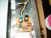
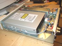
My drive is now working the way it should. I replaced the transport with one from a different drive and my distortion problem went away. The sound is surprisingly good. The pic shows how I currently have it setup. I used cat5 to get the signal from the CXD2510Q to the TDA1543A. It exits through a notch I made in the cdrom chassis and is strapped to the cdrom. The holes in the case next to DAC board are for a future TTL to SPDIF board which is the next project. That will allow me to compare the sound with the on board DAC and an external one (also in the works). I am also planning a linear power supply to replace the switching one. Another thing, Removing the back piece of plastic trim really helps with the heat issues inside the cdrom. It pops right off. Progress has been slow with so many other projects, but when the ball gets rolling its hard to stop.
Thanks for everyone's help
Dave
Thanks for everyone's help
Dave
Attachments
- Status
- Not open for further replies.
- Home
- Source & Line
- Digital Source
- Schematics for NEC 602 CDROM Drive?