mooreamps,
That is a very good point about the 45 tube's grid bias, and transconductance.
And that is at one specific set of quiescent parameters.
In the 45 datasheet, there are 3 'sets' of quiescent plate voltage, plate current, grid bias, and transconductance values, for a single ended 45 output stage.
But transconductance is somewhat constant versus plate voltage, plate current, and grid voltage.
But we are driving a plate load, the output transformer.
And what does change drastically is the slope of the plate curves (the plate impedance, rp).
1. With less negative grid voltage, the rp decreases.
2. With more negative grid voltage, the rp increases.
The u of the 45 is somewhat constant.
But the gain of the output stage is RL/(RL + rp) x u.
the gain changes quite a bit, over the range of grid voltage, from 0V to quiescent volts, to 2X the quiescent volts.
Putting 1. and 2. together, that sounds like the dominant 2nd harmonic distortion of a single ended 45 output stage, which is what we know it has.
To prove that you need more than +/- 18V to drive a 45 output stage, start with any of the 3 datasheet quiescent conditions. Then draw the appropriate load line from that datasheet quiescent condition, and place it on the set of curves.
You will find that the tube plate voltage goes up, as the tube current essentially cuts off when the grid goes to -2X the quiescent grid bias voltage.
You will find that the tube plate voltage is still decreasing, and the plate current is still increasing; as the grid goes from quiescent bias, all the way to 0V.
Check the grid voltage range from 0V, to quiescent bias volts, to perhaps 1.8X or 1.9X of the quiescent bias volts.
Look at the signal output to the output transformer primary over the range of grid volts. That will be the approximate range of useful signal drive to the 45 grid.
It will be much larger than +/- 18V.
Lets say we will use a driver that swings +/- 80% or +/-90% of the quiescent bias voltage, as the linear portion. That is far more than +/- 18V.
That is why we draw load lines on the set of plate curves, it tells us what the tube will do under those conditions.
Of course, we have to make a judgement call, and decide what portion of that signal drive is reasonably linear, or at least useful.
But to restrict the drive to +/- 18V peak is a waste of a 45 tube.
Last edited:
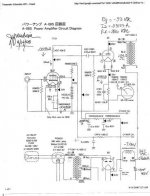
Ah, thanks. By the way, I found a more readable copy here. I feel like a hacker now.The attached -poorly visible- schematic contains little larger measured values, but within 10W border.
Here's a well respected 45 SET designed by Gordon Rankin called the Bugle. It walks you through the design process, including the math details, quite well. You might want to consider it as an alternative. I built a budget version years ago as my first DIY build.
Thanks a lot for this file! It will take a few reads to digest, but in just four pages it explains a lot of the things I have been wondering about.
I have been trying to decide between the Yamamoto and the JE Labs Simple 45 / 2a3, Now the Bugle might be a third option. Any way it goes, this article is definitely a reference.
You're welcome . . . It's the only 45 SET I've built so I can't say how it compares but lots of people seem to have built it and it gets excellent reviews.Thanks a lot for this file! It will take a few reads to digest, but in just four pages it explains a lot of the things I have been wondering about.
I have been trying to decide between the Yamamoto and the JE Labs Simple 45 / 2a3, Now the Bugle might be a third option. Any way it goes, this article is definitely a reference.
It sounds great, even though I built a "budget" version by using scrounged transformers to keep the cost down. In this case, the PT is from a 1930s Philco radio and the OTs were pulled from a Montgomery Wards Airline console stereo that used SE 7868 outputs.
mooreamps,
It will be much larger than +/- 18V.
Lets say we will use a driver that swings +/- 80% or +/-90% of the quiescent bias voltage, as the linear portion. That is far more than +/- 18V.
That is why we draw load lines on the set of plate curves, it tells us what the tube will do under those conditions.
Of course, we have to make a judgement call, and decide what portion of that signal drive is reasonably linear, or at least useful.
But to restrict the drive to +/- 18V peak is a waste of a 45 tube.
Well, I don't work with the 45 tube, so I have no basis for comparison. I only see what was captured in the data sheet.
mooreamps,
I could not find any 45 datasheet that states the grid drive is only +/- 18V.
Where did you find a text that said to take the quiescent current, divide it by the mA/V, in order to get the usefull peak grid drive?
You can not just use only the transconductance and quiescent current, and no other factors to find the useful grid drive voltage range (between 0V and just before cutoff).
56V/18V = 3.1 The usable grid drive range is far more than 1/3 of bias.
Or,
Start with a 2A3 with a quiescent setting of -45V bias, 2500 Ohm load, 250V plate, 60mA, and 5.25mA/V.
60mA/(5.25mA/V) only gives a peak grid swing of 11.4V. That is not how you find the required useful grid drive on a 2A3.
Use the 2A3 plate curves, put a dot on the plate voltage and current, and draw the load line. Look from 0V grid to almost all the way to 2X the bias.
The useful 2A3 grid drive is a whole lot more than +/- 11.4V.
Last edited:
Another way to put it.
Some tubes have graphs with mutual conductance as a function of some other parameter. you can find the S for a certain operating point by drawing an intercept line. S or mutual conductance is the product (Y/X) of the intercept line.
In conclusion: mutual conductance is only valid for a known operating point.
In some tube testers, S is measured using a 450mV or smaller sine, and the IA run through a bandpass filter to get rid of Harmonic distortion. (L3-3)
BJT”s have something similar, where you use the derivative of the HFE for calculating the small signal current gain.
Cheers,
- Status
- This old topic is closed. If you want to reopen this topic, contact a moderator using the "Report Post" button.
- Home
- Amplifiers
- Tubes / Valves
- schematic from this amp 45/717a/5u4..