Thanks euro21. That would be a slightly different design, right?
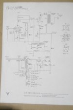
Speaking of CLC, I notice that ThorstenL's diagram is different from the Yamamoto manual page in the first capacitor (C1) value: 20 vs. 40µF. I couldn't verify the value from photos since that's the upright, above chassis one. Which one is right?
Speaking of CLC, I notice that ThorstenL's diagram is different from the Yamamoto manual page in the first capacitor (C1) value: 20 vs. 40µF. I couldn't verify the value from photos since that's the upright, above chassis one. Which one is right?
You can build a 45 amplifier with a 30mA output transformer.
Just back off quite a bit from 36mA in the tube data.
But you can not build a Yamamoto A-08 using a 30mA transformer.
Vp 352V, V self bias 56.5V.
352V - 56.5V = 295.5V
56.5V self bias / 1500 Ohms = 37.7mA (significantly too much for a 30mA Output Xfmr).
37.7 mA x 295.5V = 10.9 Watts plate dissipation.
The Yamamoto amplifier runs the 45 really hard.
295.5V at 37mA, 10.9 Watts,
versus 45 data sheet: max plate voltage, 275V, max plate dissipation 10 Watts
Last edited:
Which one is right?
Original schematic (I have another scanned copy, but also poorly visible) shows 10uF.
You can build a 45 amplifier with a 30mA output transformer.
Just back off quite a bit from 36mA in the tube data.
But you can not build a Yamamoto A-08 using a 30mA transformer.
Vp 352V, V self bias 56.5V.
352V - 56.5V = 295.5V
56.5V self bias / 1500 Ohms = 37.7mA (significantly too much for a 30mA Output Xfmr).
37.7 mA x 295.5V = 10.9 Watts plate dissipation.
The Yamamoto amplifier runs the 45 really hard.
295.5V at 37mA, 10.9 Watts,
versus 45 data sheet: max plate voltage, 275V, max plate dissipation 10 Watts
I just got a pair of One Electron UBT-2 that lists the 45 at 250V plate voltage, 36mA plate current. Max primary current is 110 mA. I am not sure how to apply your calculation to these specs, would the UBT-2 work with this setup?
Thanks.
Last edited:
Ugh, that's confusing... Plus I saw this other set of pictures from a 2009 Yamamoto kit with the second C in the CLC at 100µF instead of 47.Original schematic (I have another scanned copy, but also poorly visible) shows 10uF.
gattu marrudu,
I built a stereo 45 single ended amplifier, and I used the One Electron UBT-2 transformers (4800 Ohm primary).
I used closer to 275V plate to filament. The bias was about -56V. That requires about 331V B+, a little bit more if you compensate for the drop in the UBT-2 DCR (about 400 Ohms). 34mA x 400 Ohms primary DCR = 13.6V drop from the B+ voltage. The 820 Ohm common bias resistor gave 34mA per 45 tube, 68mA total (I only had one filament winding, so I could not use individual self bias 1600 Ohm resistors that I wanted to).
I only had used 45 tubes, not new old stock (NOS), they did not have 36mA per plate in that amplifier.
I used a dual triode input /driver tube, one triode for each 45.
It only put out about 1.5 Watts, not too bad for the old used tubes.
If you uses 250V from the plate to the filament, you will only get 36mA if you use bias voltage that is Less than 56V.
I gave away my UBT-2 transformers.
But I have some nice Electra Print Audio 5k Ohm transformers, I may again build a 45 amp.
Or I may build a mono-block parallel single ended 45 amp, using a One Electron UBT-3, 3k transformer.
Have fun building and listening to a 45 amplifier.
Last edited:
Konnichiwa,
I have decided to post the Schematic in another on-line group with pretty complete detail, so also find it here, in context. It is basically 99%, one or two values may be slightly different, but not much.
If you want to copy the Amplifier you do of course need the iron, considering fit/finish, component quality and inclusion of NOS Valves I'd think it's worth giving Yamamoto the business and buying the Kit if you want to build the Amplifier, a Set of Tamura Transformers and a nice case plus the valves will take most of the cost of the kit.... ;-)
Sayonara
Too many design flaws.
Ugh, that's confusing... Plus I saw this other set of pictures from a 2009 Yamamoto kit with the second C in the CLC at 100µF instead of 47.
..... and that is a problem ? On Surface amplifier, I run 100uf / 30H / 100 uf , for the plate supply.. have not seen any issues. I could run more, but it's a part cost vs performance, and these values work pretty good enough....
Zener string has its advantages: easy to calculate gain for a bogey tube: disadvantage : circuit performance deteriorates as the tubes age.
If you use a resistor divider with 100n-1u film to ground for G2 on the C3m your circuit becomes more tolerant to tube aging. Because as the tube ages the G2 current decreases, this will increase the voltage on G2 somewhat and keep the gain stable over time.
The drawbacks of this approach is that you need to know how to do a thevenin equivalent circuit of a voltage source with a resistor in series. You then eyeball the current from the graphs and plug those in to the circuit.
But i think the EC86 10M45S loaded is much nicer...
..... and that is a problem ? On Surface amplifier, I run 100uf / 30H / 100 uf , for the plate supply.. have not seen any issues. I could run more, but it's a part cost vs performance, and these values work pretty good enough....
This is my first amp project not from a complete kit, so I have a very basic (to put it mildly) understanding of the math and I'm trying to stick to the design. The only variable that I have to change is the OPTs that I just bought for another 45 project before changing my mind and started getting materials for the Hashimoto design.
Having read elsewhere that the capacitor values in the PSU are best closer to spec, I'm kind of confused about which values I should follow. At this point, following the original manual seems the safest bet. Forgive the newbie's confusion...
OK, really stupid question here: can I just replace the 200K signal resistor with a potentiometer and hook up a line stage directly, or do I need a proper pre?
Thanks again
gm
Thanks again
gm
Yamamoto kit with the second C in the CLC at 100µF instead of 47.
It's a kit version, so anything can happen. 😛
The original shows 47uF.
Attachments
gattu marrudu,
The 45 has -56V bias.
In order to get full output out of the amplifier, the driver has to drive the 45 grid with a signal range of +56V to -56V (112V peak to peak).
I do not know of any "line stage" that has 112V peak to peak.
You need a volume control before the driver stage, and the driver needs to swing 112V peak to peak.
A typical CD player full scale output is 2.1Vrms (-3V to +3V, or 6V peak to peak).
112V peak to peak out / from 6V peak to peak in = 18.7, the minimum gain required from the driver to get full amp output from full scale CD player output.
If the CD is a quiet one, you will not get full wattage from the 45, unless the driver has more gain than 18.7.
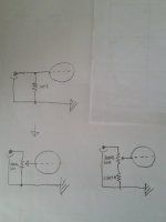
OK, really stupid question here: can I just replace the 200K signal resistor with a potentiometer
Theoretically yes ... but when potmeter wiper not contacting correctly, the tube grid potential undefined (no grid leak resistor).
Usually use this layout as potmeter wiper joined to grid, but large (0.5-1Meg) grid leak resistor also in use.
gattu marrudu,
You have two each 200k resistors, one for the input stage grid, and one for the 45 grid.
I thought you meant to get rid of the whole driver stage, and replace it with a line stage and a volume control.
Silly me, that was not what you wanted to do.
You have two each 200k resistors, one for the input stage grid, and one for the 45 grid.
I thought you meant to get rid of the whole driver stage, and replace it with a line stage and a volume control.
Silly me, that was not what you wanted to do.
6A3sUMMER, yes, just the potentiometer—I have already a phono stage (Roy Mottram's PH16) and a preamplified DAC with plenty of output to drive my Audio Nirvana 300B SET and 10' full range speakers. In my small room I play the 300B at about 1/5 volume.
So, like in the attached drawing? (bottom left is my mod, bottom right your suggestion) Also would using a high quality potentiometer be enough to avoid bad surprises?
Theoretically yes ... but when potmeter wiper not contacting correctly, the tube grid potential undefined (no grid leak resistor).
Usually use this layout as potmeter wiper joined to grid, but large (0.5-1Meg) grid leak resistor also in use.
So, like in the attached drawing? (bottom left is my mod, bottom right your suggestion) Also would using a high quality potentiometer be enough to avoid bad surprises?
Attachments
Last edited:
gattu marrudu,
The 45 has -56V bias.
In order to get full output out of the amplifier, the driver has to drive the 45 grid with a signal range of +56V to -56V (112V peak to peak).
.
I am not so sure about that. The data sheet shows application plate current of 36 milliamps and a transconductance (gm) of 2ma/V. This would suggest plate current saturation/cutoff occurs at +/- 18 volts (peak).
Here's a well respected 45 SET designed by Gordon Rankin called the Bugle. It walks you through the design process, including the math details, quite well. You might want to consider it as an alternative. I built a budget version years ago as my first DIY build.This is my first amp project not from a complete kit, so I have a very basic (to put it mildly) understanding of the math and I'm trying to stick to the design. The only variable that I have to change is the OPTs that I just bought for another 45 project before changing my mind and started getting materials for the Hashimoto design.
Having read elsewhere that the capacitor values in the PSU are best closer to spec, I'm kind of confused about which values I should follow. At this point, following the original manual seems the safest bet. Forgive the newbie's confusion...
The Bugle uses a choke input PS but if you're using a cap input you need to look at the data sheet for your intended rectifier tube. The basic value for the first cap is listed in the spec table. If you scroll down further, they often have 3 charts which can be used to determine if your specific design can safely use a particular (possibly larger) cap value. The charts are like a 3 part test and if your design passes all of them then your cap value is acceptable.
One practical concern of using a larger value is that current production rectifiers have a reputation for not being nearly as tough as old production, even though they claim to meet the same specs.
It's also a good idea to use PSUD2, which is a free download, to simulate the PS. You can then make an informed decision whether using a larger cap is an acceptable trade off, since it will put more stress on the rectifier tube.
Attachments
Last edited:
bottom right your suggestion
I think you misunderstood.
Leave grid leak resistor, but increase its site to 470k.
Use 100k pot, wiper tied to grid, "ground" to amplifier "ground".
- Home
- Amplifiers
- Tubes / Valves
- schematic from this amp 45/717a/5u4..