Just because there is a spot for them on the board doesn't mean you can't run leads out to front panel LEDs. For that matter, there is no reason that the LEDs are required if you have some other power on indication.
Good idea for a single trim pot.
Speak up, the rest of you!
Good idea for a single trim pot.
Speak up, the rest of you!
I mailed Bob a set of PDFs.
Bob please post them after review and let everybody rewiev and ok the data for production.
Thanks
\Jens
Bob please post them after review and let everybody rewiev and ok the data for production.
Thanks
\Jens
Bob,how much current did you draw while testing the psu?
Looking at Jens's pictures the caps for C4,C5 seem very small.
If they are only 680uf they are too small for the current you drew.
Checking out dimensions for Panasonic FC's you could go as high as 3900uF per capacitor.This would lower the ripple significantly.
I personally will put the biggest capacitors that will fit on the board.
When using a 18 V transformer the voltage of the caps should be upgraded to 35V.
kro5998
What is the size and voltage rating and price of the 3900µF caps?
I have not looked close to find the biggest cap that would fit, but if anyone has suggestions to parts that fit the current board, please step forward so the BOM can be updated.
\Jens
I have not looked close to find the biggest cap that would fit, but if anyone has suggestions to parts that fit the current board, please step forward so the BOM can be updated.
\Jens
I'll let Jens answer the question about current draw during testing, as I have not built my prototype yet.
We could go up to 2700 uf / 35 V in the same 16mm od form factor. That increases the cost of the parts kit by $4.25.
Comments on increasing the cap value?
We could go up to 2700 uf / 35 V in the same 16mm od form factor. That increases the cost of the parts kit by $4.25.
Comments on increasing the cap value?
Caps: The bigger the better.
I used 2 x 470 µF during the testing (what I had in my box of caps)
\Jens
I used 2 x 470 µF during the testing (what I had in my box of caps)
\Jens
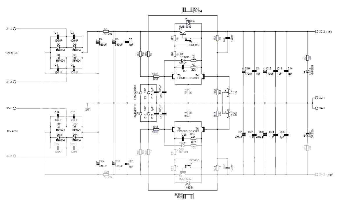
I simulated the main filter with PSU designer. Even with 2700 uf-1R-2700uf, there is barely enough voltage for the regulator to work at 500 mA using 15V input. We need the next standard higher voltage transformer, 18V.
With 18V input and 680 uf, we end up with 3.5V of ripple going into the regulator at 1 amp, and about .75V for the regulator to work - the bottom of the ripple is 17V. at 1 amp. The ripple stays above 20V at .5A, so this would do for a light load economy version.
At 1200 uf in the CRC the 1 A ripple drops to just under 2V and the bottom is >18V. The .5A ripple stays above 20.5V
At 2700 uf CRC, the 0.5V ripple stays above 17V up to 1.5A output.
I think a good compromise is to bump the kit capacitance to 1200 uf. The resulting PSU will be suitable for 1 amp output up to 15V. This will only increase the parts kit cost $1.50, instead of the $4.25 for 2700 uf.
Comments?
As we stay with the 15V transformer we can go to 3900uF in the same form factor.(EEUFC1E392L)
As the ripple is proportional to the current we don't know for shure until tested.
For me personally the 15V will do with the biggest possible caps since i will only power two filter boards.
Jens,did you measure the voltage drop over R1 and the pass device?
3 to 5 V over the pass device should be more then enough for proper regulation.Perhaps you can decrease the size of R1.
kro5998
Sorry Bob,you posted the same time i did.
I did some simulations on my situation and when using schottky's (1N5819 or 1N5822) i can do with a 15V tranny.
I did some simulations on my situation and when using schottky's (1N5819 or 1N5822) i can do with a 15V tranny.
No problem, Kro.
A lot depends on the way you model the transformer. If I plug in 16.5V, representing the no load voltage with 11% regulation, and a secondary resistance of 0R75, which drops the output voltage to 15V at rated load, even 470 uf gives >3 V for the pass device up to 360 mA (four filter boards).
However, if the particular transformer is on the low end of its 10%tolerance or the line voltage is on the low side, you will barely have 3V across the pass device, even at 200 mA using 2700 uf capacitors.
So, in the interest of reliable regulation, the group buy transformer will be 18V, and the parts kit will include at least 1200 uf main filter caps.
Here is the schematic
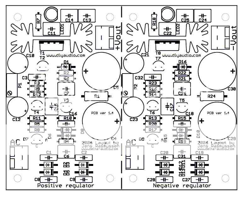
the silkscreen
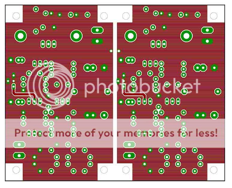
the bottom layer
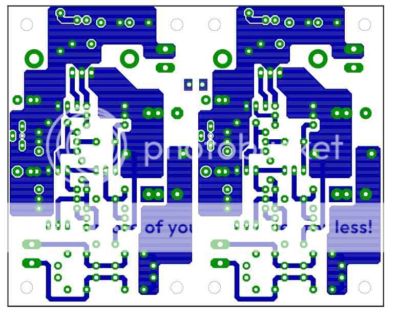
The top Layer
and the BOM
Qty Value Note Parts
4 Terminal 2.54mm pitch X1, X2, X3, X4
10 1µF 5.5X07.5mm C6, C11, C13, C14, C15, C17, C22, C24, C25, C31
12 1N4004 1N4004 D1, D2, D3, D4, D5, D6, D11, D12, D13, D14, D15, D16
2 1R 2W R1, R24
10 1k R2, R3, R5, R6, R11, R13, R20, R21, R22, R23
4 3k3 R7, R12, R14, R18
2 10V ZENER-DIODEDO35 D8, D10
4 10k R4, R8, R17, R19
2 10k B64W/B64Y P1, P2
2 22k R9, R16
2 100R R10, R15
12 100nF 2.5X07.5mm C1, C2, C3, C8, C9, C16, C18, C19, C20, C27, C28, C32
2 100pF 5.5X07.5mm C7, C26
4 470uF/25V 5.0mm pitch 8.5mm body C10, C12, C21, C23
4 680µF/35V 7.5mm pitch 16mm body C4, C5, C29, C30
3 BC546C T3, T4, T7
3 BC556C T2, T5, T6
2 GREEN LED5MM LED1, LED2
2 LM4040 D7, D9
1 MJE15032 T8
1 MJE15033 T1
2 SK104 KK1, KK2
the silkscreen
the bottom layer
The top Layer
and the BOM
Qty Value Note Parts
4 Terminal 2.54mm pitch X1, X2, X3, X4
10 1µF 5.5X07.5mm C6, C11, C13, C14, C15, C17, C22, C24, C25, C31
12 1N4004 1N4004 D1, D2, D3, D4, D5, D6, D11, D12, D13, D14, D15, D16
2 1R 2W R1, R24
10 1k R2, R3, R5, R6, R11, R13, R20, R21, R22, R23
4 3k3 R7, R12, R14, R18
2 10V ZENER-DIODEDO35 D8, D10
4 10k R4, R8, R17, R19
2 10k B64W/B64Y P1, P2
2 22k R9, R16
2 100R R10, R15
12 100nF 2.5X07.5mm C1, C2, C3, C8, C9, C16, C18, C19, C20, C27, C28, C32
2 100pF 5.5X07.5mm C7, C26
4 470uF/25V 5.0mm pitch 8.5mm body C10, C12, C21, C23
4 680µF/35V 7.5mm pitch 16mm body C4, C5, C29, C30
3 BC546C T3, T4, T7
3 BC556C T2, T5, T6
2 GREEN LED5MM LED1, LED2
2 LM4040 D7, D9
1 MJE15032 T8
1 MJE15033 T1
2 SK104 KK1, KK2
Attachments
Is this what you have in mind regarding the 431?
And should we keep the standard zener ref on board so that three different ref generators are possible.
I think it is a bit much, two choises (low cost vs high cost) are ok, but two "high cost" options and one low cost is really a waste of presious board space IMHO.
\Jens
And should we keep the standard zener ref on board so that three different ref generators are possible.
I think it is a bit much, two choises (low cost vs high cost) are ok, but two "high cost" options and one low cost is really a waste of presious board space IMHO.
\Jens
Attachments
Hi Jens & others still listening,
the D7 & D8 will both fit the TL431 pin locations (middle pin and lower pin).
You do not need to add in board space for two or three references. Just the three pin pads to allow a choice of reference type.
It would be better still if the two programming resistors feeding the tl431 adjustment pin were also put on board. I think this was Perander's suggestion.
The PCB has a bit of space in this area.
Now anyone choosing the D7 or D8 reference would fit into the two outer pin pads of the 431 location and simply omit the programming resistors.
Any other thoughts?
The TL431 Data sheet says “low noise” showing around 50 nV/root Hz
The LM4040 shows 1.8 uV/root Hz.
While the TL431 is quieter, does it matter when compared to the noise in the rest of the regulator and when the majority will be using this supply to power opamps with 100+dB PSRR?
The LM329 can be used with the layout as is and has noise performance similar to the TL431.
Is there another reason you so strongly prefer the TL431?
If you are mounting the programming resistors off board, you can just use the existing pads but reverse the orientation of your reference.
Ordering begins
Please send email to robert (dot) e (dot) ellis ( at ) Verizon (dot) net with the subject line "Group Buy"
including your:
DiyAudio? Name
Real Name
Shipping address
#of Filter boards
#of PSU boards
# of PSU parts kits (not quite finalized but probably $20.25)
# of Heat sink pairs (if you are buying OPAs from gengis he can combine with that order)
# of Tranformers
I will send you an invoice for your parts and shipping once all pricing has been finalized.
Hi,
it was others that originally suggested using 431 as an optional alternative to the fixed reference. I just supported them.
My own reasons are 431 is adjustable, it is cheap, I already have a stock.
When building regulated PSUs for power amps and active crossovers, having to buy a different reference chip is a significant cost.
- Status
- Not open for further replies.
- Home
- Group Buys
- Scalable PSU/regulator GB