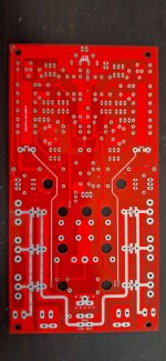
By the way looking at the PCB layout I wonder if the feedback pickoff point can be more symmetrical and avoid being tainted with half-cycle currents by changing it thus:

original:

Even a fraction of a milliohm asymmetry for the pick-off point can be quite measurable distortion... Standard 1oz copper is 0.5 milliohms per square.
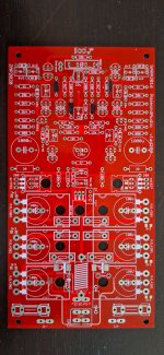
original:
Even a fraction of a milliohm asymmetry for the pick-off point can be quite measurable distortion... Standard 1oz copper is 0.5 milliohms per square.
Member
Joined 2021
Member
Joined 2021
Aprox 0.02v. For 0.02v you need a hefty heatsink. If you want a smaller heatsink, you can use a 0.005v on the BIAS measurement points, the sound is very good too.Bias volt How much?
Any type of SMD diode that fits there and has a reverse voltage greater than 100v and a maximum surge current greater than a few dozen amps. You might as well not put them at all as long as you are careful and do not supply the modules with reverse voltages. Those diodes are also called "anti-fool" diodes. They do not play an essential role in the operation of the amplifier, they just offer a greater degree of protection against carelessness during assembly.
Hi everyone,
I've been reading and learning about this project for a while. Some years ago, I also purchased a few PCB kits along with MJL4281A/MJL4302A and MJE15032G/MJE15033G transistors, together with a friend who initially introduced me to the project and was excited to build it.
However, due to various reasons and my lack of experience in electronics (zero), I ended up postponing the work.
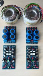
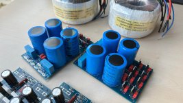
After all these years, I've finally decided to start building this amplifier, and this is were I got.
My question is: Will the Moderate Speed version work with the MUTE / REED NC section?
I'm asking because I noticed a comment from Raimond stating:
Does this mean I should leave them as they are, or completely remove them? I just want to confirm before proceeding.
Thanks!
I've been reading and learning about this project for a while. Some years ago, I also purchased a few PCB kits along with MJL4281A/MJL4302A and MJE15032G/MJE15033G transistors, together with a friend who initially introduced me to the project and was excited to build it.
However, due to various reasons and my lack of experience in electronics (zero), I ended up postponing the work.
After all these years, I've finally decided to start building this amplifier, and this is were I got.
My question is: Will the Moderate Speed version work with the MUTE / REED NC section?
I'm asking because I noticed a comment from Raimond stating:
"You can remove 'REED NC' and 'MUTE' entirely. Do not touch them. You can use the 'SARA-2016 Moderate Speed' schematic."
Does this mean I should leave them as they are, or completely remove them? I just want to confirm before proceeding.
Thanks!
Attachments
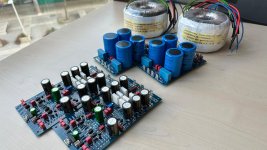


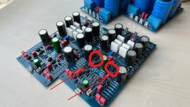
I recommend you to remove the rubber cap that sticks the VAS two transistors. There is no need to work at the same temperature. They get quite hot and need adequate ventilation. If you find it, it would be useful to put radiators for TO-92.
https://www.google.com/search?num=1...0HHY1aFiQQtKgLegQIChAB&biw=1866&bih=912&dpr=1
https://www.google.com/search?num=1...0HHY1aFiQQtKgLegQIChAB&biw=1866&bih=912&dpr=1
Attachments
Thanks a lot for clarifying these details @greierasul . I will remove the heat-shrink sleeves and try to get some heat sinks.
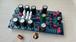
One question regarding the LR: does it need to be exactly 1.5 µH, or is there a margin? I also noticed that some colleagues split the component by putting the resistor under the board and the inductor in the marked location.
Thanks for sharing this project! And here I would like to include Alex and the rest of the contributors.
Attachments
Okay! I’ll put the resistor underneath and place the coil in its designated spot.
I just remembered something about the resistors: I couldn’t find a 250 kΩ resistor, so I used 240 kΩ. For the 20 Ω resistor, I used 22 Ω. And for the 500 Ω and 800 Ω resistors, I used 520 Ω and 820 Ω, respectively. All of them have a 1% tolerance. Will this work well, or should I switch them out now that I’ve found the exact values?
I just remembered something about the resistors: I couldn’t find a 250 kΩ resistor, so I used 240 kΩ. For the 20 Ω resistor, I used 22 Ω. And for the 500 Ω and 800 Ω resistors, I used 520 Ω and 820 Ω, respectively. All of them have a 1% tolerance. Will this work well, or should I switch them out now that I’ve found the exact values?
Member
Joined 2021
Member
Joined 2021
Member
Joined 2021
I want to use two exponential potentiometers for this project, with large knobs around 40 to 50 mm in diameter. However, I’m not entirely sure about the specifications they should have. Could they be 10 kΩ? I’m also considering motorized potentiometers or even a single stereo pot.
- Home
- Amplifiers
- Solid State
- SARA-2016