We have used the IL260 isolators for interfacing between the ADC and FPGA or Microcontroller and those work well. For slower speeds have used the HCPL2630 optoisolators. We monitor the current pulse into high power LEDs during testing to determine bonding to the substrate. We've used the INA103 (differential). Current speed (older design) is ~100ksps, but newer parts require from 250ksps to 1Msps. The LTC2500 is vastly configurable - averaging of 4 samples gives 250ksps and a range of 109db with 13uV of noise- if the front end circuitry is capable of equal performance.
The LTC2500 when sampling at 1Msps has an impedance of about 20K so buffer is still needed. Still trying to decide if this is best one to use.
The LTC2500 when sampling at 1Msps has an impedance of about 20K so buffer is still needed. Still trying to decide if this is best one to use.
Hello,
I have received some transformers and i made some pulse response tests
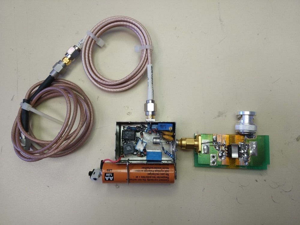
using a DIY pulse generator with less than 100pS rise time and 20ns duration.
A picture of the pulse generator and the DUT test board.
I tested three transformers (others coming but not yet received) ;
Scientific conversion SC947-02 (audio)
Wurth 749020100A (LAN)
Wurth 749010310 (LAN)
For all tests, signal level is set to about 500mVpp at transformer input
with impedance adapted to 75 Ohms on each side (I made this choice to be same
as SPDIF audio link, but that could be 100 or 50 Ohms).
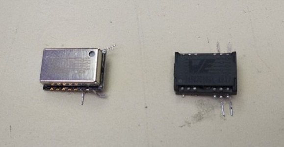
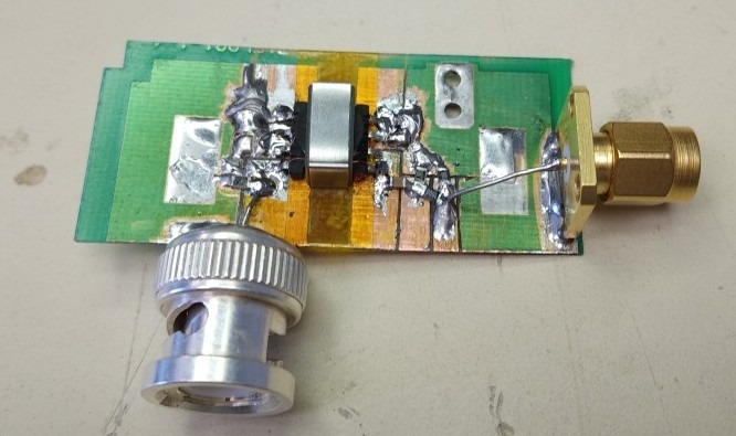
One picture of the two wurth LAN transformer and the SC947-02 mounted
on DUT PCB.
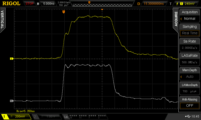
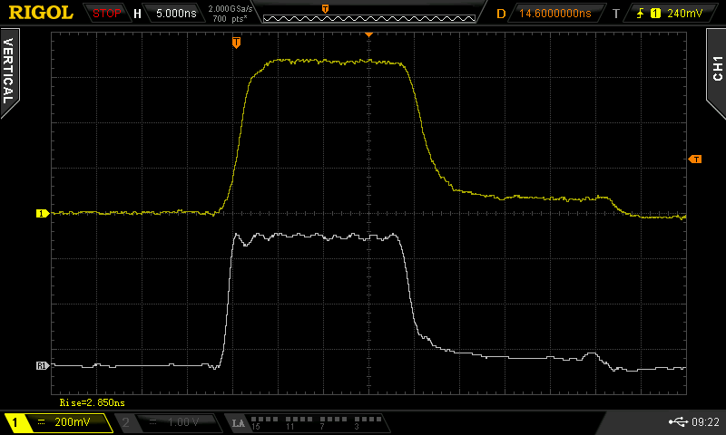
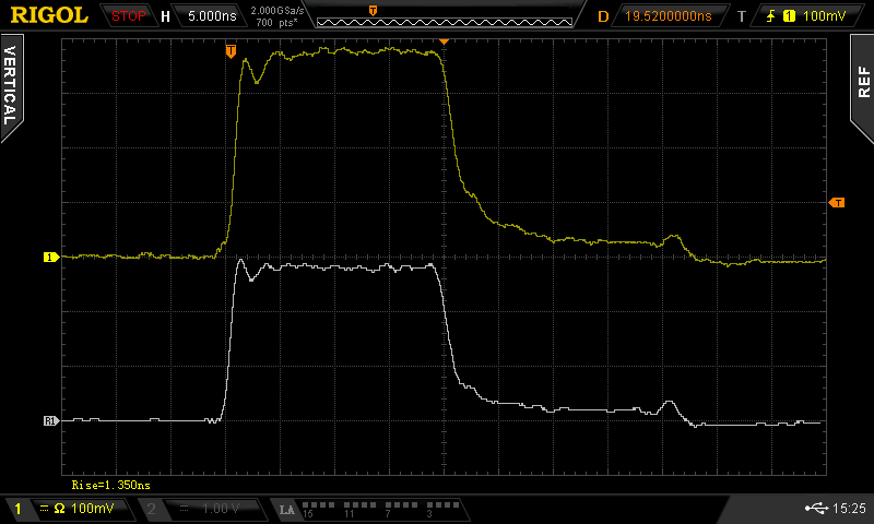
Now the pulse test results (gray trace is generator alone as reference) :
SC947-02
Wurth 749020100A
Wurth 749010310
These first results speak by themselves...
The last wurth LAN transformer work very well and output pulse rise time
look same as input and waveform is very clean.
We must note that this transformer is much cheaper than the SC947-02.
I will post soon others results, and of course i work a lot to complete
the AA2380 schematic in the next weeks.
To follow...
Frex
I have received some transformers and i made some pulse response tests
using a DIY pulse generator with less than 100pS rise time and 20ns duration.
A picture of the pulse generator and the DUT test board.
I tested three transformers (others coming but not yet received) ;
Scientific conversion SC947-02 (audio)
Wurth 749020100A (LAN)
Wurth 749010310 (LAN)
For all tests, signal level is set to about 500mVpp at transformer input
with impedance adapted to 75 Ohms on each side (I made this choice to be same
as SPDIF audio link, but that could be 100 or 50 Ohms).
One picture of the two wurth LAN transformer and the SC947-02 mounted
on DUT PCB.
Now the pulse test results (gray trace is generator alone as reference) :
SC947-02
Wurth 749020100A
Wurth 749010310
These first results speak by themselves...
The last wurth LAN transformer work very well and output pulse rise time
look same as input and waveform is very clean.
We must note that this transformer is much cheaper than the SC947-02.
I will post soon others results, and of course i work a lot to complete
the AA2380 schematic in the next weeks.
To follow...
Frex
The only method is by lowering the bandwidth to 5sps or less, and even then it's only 28 bits or so. We need as much resolution as possible for precision current monitoring at up to 1Msps, a bit different. Have used parallel amps to lower noise and moving window averaging, but need still better performance. Fortunately our source is low impedance - 5 ohms or less. The INA103 has excellent linearity but is pretty old now.
Search around for Gerhard Hoffmann's (username "gerhard") preamp designs for low noise PSU measurements. His stuff is probably the closest public domain (at least here, I haven't looked around the greater interwebs for heroic preamps) for getting a high ENOB-preamp at low source impedences.
Exceptional results, thank you. I have done high speed pulse generators (10ns) for laser diode work with somewhat different techniques, and have used terminated coax cable for very clean sub-nanosecond pulses by discharging the charged length of cable into the load.
Following earlier posts we are currently designing an interleaved system to achieve higher sample rates while minimizing noise. It does require an FPGA to move data to memory to achieve the highest rates.
Following earlier posts we are currently designing an interleaved system to achieve higher sample rates while minimizing noise. It does require an FPGA to move data to memory to achieve the highest rates.
I guess that beast doesn't fit into the standard Hammon case? P.S. the
Würth 749010310 is the best.
Würth 749010310 is the best.
Before you can "crown" one the best you need to fully define the application and then the requirements for the transformer.
SPDIF needs extended response, low return loss and good isolation. Moving a clock may work best with a narrow band tuned transformer. Without details on the application you can focus on the wrong aspects.
SPDIF needs extended response, low return loss and good isolation. Moving a clock may work best with a narrow band tuned transformer. Without details on the application you can focus on the wrong aspects.
My request for an external clock input was for being able to use non-standart sampling frequencies. So there is no specified frequency to which narrow tuning would apply to.
Demian,
I fully agree. It is only a partial result for these transformers and how it performs with fast pulse test.
It is obvious that their real performance is not just about this.
Anyway, i thanked interesting to share these partial results, others test will be done soon.
You can already look manufacturer data of each transformer here
(Wurth give extended data with return loss and CMRR) :
Scientific conversion SC947-02 (audio)
Wurth 749020100A (LAN)
Wurth 749010310 (LAN)
In my mind, the transformer requirements would be :
Fast rise time
10-100MHz frequency response (clock signal can be up to 100MHz)
High CMMR
Low inter winding capacitance
High isolation
Low return loss
Low Cost ( as possible)
Easy to find
To improve signal recovery and reduce jitter, i use LVDS differential
receiver on secondary side of transformer.
Zfe,
The nominal output sampling rate output of the AA2380 board are 48/96 and 192kHz.
The real ADC sampling rate can be up to 32 time higher because of SinC filter active (if enabled).
Note that this limitation i only for stand alone mode (this board only),
but with the external AA10M08 board it can be possible to use full sampling rate
up to 1536kHz on both channels (What would you require as sampling frequency ? ).
Note also, that others sampling frequency are possible (only software)
but you must keep in mind that you need an interface that can be able to work with
(standard audio interfaces only support some sampling rate).
diyralf
I think that the AA2380 board will fit well in a Hammond enclosure,
but only for stand alone operation (without others board).
This is not already well defined yet.
Frex
Are there PC card interfaces up to 1.5 MHz? I guess, 192k would be the limit.The real ADC sampling rate can be up to 32 time higher because of SinC filter active (if enabled).
Note that this limitation i only for stand alone mode (this board only),
but with the external AA10M08 board it can be possible to use full sampling rate
up to 1536kHz on both channels (What would you require as sampling frequency ? ).
Hello,
Not as i know diyralf (i have seen the RME ADI-2 Pro FS that support 768kHz analog input recording )...
Anyway,there is possibility to send 4 x 192 kHz data stream with the USB-streamer and then
reconstruct sliced data to computer.
I remember that HpW from here have already done this on it's FFT software (HpW works).
So the AA2380 is able to provide 4 channels sliced data to get real direct 768 kHz data rate.
Frex
Last edited:
SPDIF is limited to 192K although you could do a dual link to get 384K. But I hate dealing with dual link stuff, its really clumsy. USB can support up to 768K and even 1.5 MHz with customized drivers (relatively simple in Linux, not so in Windows) but you do need software. People are already doing this in playback for DSD and DXD and some other crazy stuff. The file sizes get crazy, rivaling BluRay for size.
I suspect Virtins and HpW Works could support it pretty easily. Not to mention National Instruments who may already have solutions but for $$$$.
I suspect Virtins and HpW Works could support it pretty easily. Not to mention National Instruments who may already have solutions but for $$$$.
Zfe,
The nominal output sampling rate output of the AA2380 board are 48/96 and 192kHz.
The real ADC sampling rate can be up to 32 time higher because of SinC filter active (if enabled).
Note that this limitation i only for stand alone mode (this board only),
but with the external AA10M08 board it can be possible to use full sampling rate
up to 1536kHz on both channels (What would you require as sampling frequency ? ).
Note also, that others sampling frequency are possible (only software)
but you must keep in mind that you need an interface that can be able to work with
(standard audio interfaces only support some sampling rate).
I would like to have the possibility to tune the sample rate to a multiple of the test signal, e.g. to have the possibility to do fft without needing a window function.
If there is no audio interfaces supporting flexible sample rates, one could get the data as serial data via USB like here USB data transfer in VHDL. Perhaps this can even be implemented directly in AA10M08 board.
For analyzing the data in Mathlab/Octave it does not need to come from a audio interface.
I would like to have the possibility to tune the sample rate to a multiple of the test signal, e.g. to have the possibility to do fft without needing a window function.
[...]
Using DiAna as analyzer, no need to fiddle with the sampling rate. Indeed, it works even better when the sampling rate is not a whole multiple of the test signal frequency. Why? Read this: DiAna, a software Distortion Analyzer
Cheers,
E.
DiAna is Windows only and does not run in Wine - so no go.
Moreover I prefer to to process the data myself, if needed.
The option of unwindowed FFT was only an example. It can not harm to have full control over the sampling rate.
Moreover I prefer to to process the data myself, if needed.
The option of unwindowed FFT was only an example. It can not harm to have full control over the sampling rate.
DiAna itself works fine under Wine. It's the 32bits version of WineASIO (or JACK?) that's buggy.DiAna is Windows only and does not run in Wine - so no go.
So do I. 🙂Moreover I prefer to process the data myself, if needed.
Okay.The option of unwindowed FFT was only an example. It can not harm to have full control over the sampling rate.
Cheers,
E.
OSVA project update - AA2380 Beta schematics released !
Hello,
Some good news today, i post the first release of the AA2380 schematics (Ouf !).
I think it is nearly complete even if a deep check must be done.
I start to import the schematics on Kicad PCB and check all footprints and 3D model.
Some majors parts has been already orders.
So, now some time to learn about Kicad PCB ! 🙂
Comments welcome.
Frex
Schematics can be downloaded here : AA2380V1_Beta101118.pdf
Nice! There are many circuits now for power stabilisation - why just TPS7A...? Not that there is something bad with it - just curious!
//
//
Nice job! Take care about connecting the clock oscillator directly on the analog 3.3va power, as it rather belongs to the epld. Check also the spdif outputs in this regard.Hello,
Some good news today, i post the first release of the AA2380 schematics (Ouf !).
I think it is nearly complete even if a deep check must be done.
I start to import the schematics on Kicad PCB and check all footprints and 3D model.
Some majors parts has been already orders.
So, now some time to learn about Kicad PCB ! 🙂
Comments welcome.
Frex
Schematics can be downloaded here : AA2380V1_Beta101118.pdf
Otherwise I like it very much! Maybe you could connect sdi of the ad's to the epld as well (if you have any spare pins), later on it could add some flexibility reaching the adc internals.
Regards
Attila
Well,
all on your Analog & ADC board has the same ground, as
. Input
. Relays
. Digital
. ADC
Consider to group & split the required grounds in different groups ... while a simple relays current would/may induce ugly current within the input ground..
May also consider multiple PCB ground layers ..
At the end symmetric/asymmetric input measurements will tell you how good the PCB implementation is. 😀
just my 2 cents
Hp
Hi Frex,
A couple of comments could be that:
- it looks as if the CNV signal passes through some ICs before reaching the CNV input. Although I realize that SAR converters are less prone to phase noise than delta-sigma converters I personally would do my best to ensure that this signal is as clean as possible (low phase noise ICs etc.). Andrea Mori's thread on the well-tempered clock has some info on this.
- Second I notice that you use regulators that are just reasonably low-noise. Might it be an idea to use something like e.g. LT3042? In my experience the LTC2380 is quite sensitive to the noise input to its various PSU pins.
- The layout made by LT themselves has some validity. Just by moving and slightly re-arranging capacitors around the Vdd and IOVdd pins to reflect LTs layout (spacing of the Vdd & IOVdd ground) I got a distortion reduction on the order of -15 dBs. I reckon what happens here is that ground return paths from the digital side may influence the ground potential on the Vdd pin.
Cheers,
Jesper
- Home
- Design & Build
- Equipment & Tools
- SAR ADC for high performance audio ADC project [LTC2380-24]