Another tip...R032 (that on the left) reads ok? it feeds the COM node of the adjustment.
Last edited:
I didn't lift a leg, but in circuit it reads as in service manual.Another tip...R032 (that on the left) reads ok? it feeds the COM node of the adjustment.
Thanks for all your suggestions guys, over the week I am going to lift all the resistors to confirm.
@restorer-john I have already replaced this previously (with a 50V rating). Just now, I have confirmed that it is continuous on the negative side with the WHT wire, and the positive side is continuous with C10.
Actually, I have trouble imagining how the switch works? It has 2 white wires (I assume from the power supply) but it doesn't seem to be directly connected to the 3-way selector. Are they supposed to be decoupled or am I not seeing a connection between them?
Hi, the Switches are Just mechanicaly connected to the 3 way selector!
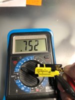
I Just finished the repairing of my 525. Main Problem was the yellow powerswitch. In closed State it hat a Résistance of 800 Ohms.

Resultate Output voltage 17 and -4,7 Volts.
I removed the switch and shorten the two white wires for testing.
Testing process:
The 3 way selector in off postion.
Then Plug in.
The motor should Starts Running as fast as it could, because of no Speed regulation is activ . Voltage is 18 V and - 4,9 V .
Voltage messurament was done After i also replaced the 3 Elcos on the Power Board.
If you Switch to 33 or 45 it should reduce the Speed. If you Just testing the Motor without the plate , the Motor stutters in 33 or 45 Mode. That’s normal , the smooth Rotation Just came up with the Weight of the plate.
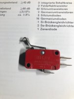
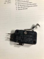
I found an simular Switch in my „grabbelkiste“. It‘s from an old Radio Flipclock, but i think you could them as New or NOS Part.
Replacing the 3 Elcos from the Power section should be a Good idea.
Good luck
Regards Tim
I Just finished the repairing of my 525. Main Problem was the yellow powerswitch. In closed State it hat a Résistance of 800 Ohms.

Resultate Output voltage 17 and -4,7 Volts.
I removed the switch and shorten the two white wires for testing.
Testing process:
The 3 way selector in off postion.
Then Plug in.
The motor should Starts Running as fast as it could, because of no Speed regulation is activ . Voltage is 18 V and - 4,9 V .
Voltage messurament was done After i also replaced the 3 Elcos on the Power Board.
If you Switch to 33 or 45 it should reduce the Speed. If you Just testing the Motor without the plate , the Motor stutters in 33 or 45 Mode. That’s normal , the smooth Rotation Just came up with the Weight of the plate.
I found an simular Switch in my „grabbelkiste“. It‘s from an old Radio Flipclock, but i think you could them as New or NOS Part.
Replacing the 3 Elcos from the Power section should be a Good idea.
Good luck
Regards Tim
Hi Tim,
To clarify, after replacing the switch, you are getting 18V and -4.9V, and the speed is 33rpm and 45rpm?
Danke.
To clarify, after replacing the switch, you are getting 18V and -4.9V, and the speed is 33rpm and 45rpm?
Danke.
I did a little Research. On yt there is a nice repair of a 525 . He Also recaped all , but at the end he figured out That the yellow Power Switch is faulty.
Great, I will try that Tim! I have recapped the whole board to no avail.
However can I ask, how to remove the switch? Do I have to fully remove most of the wooden bottom panel?
Thank you.
However can I ask, how to remove the switch? Do I have to fully remove most of the wooden bottom panel?
Thank you.
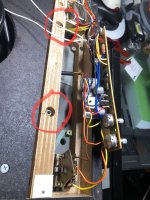
No, you just need to loosen the narrow board with the two nuts. After That you could lösen the Switch.
Is it running if you shorten the wires?
Is it running if you shorten the wires?
Yes, it runs, but the last time I did it, I did not disconnect the switch out of circuit. I am trying that next. Thanks Tim!
Unfortunately, I think I made things worse. Removed the switch completely and connected the wires together, and it's now running at 66 rpm! Something must have came loose.
It is still outputting 17.5V , didn't manage to the check the negative voltage yet. The zener diode reference is still 5V though. Sigh.
It is still outputting 17.5V , didn't manage to the check the negative voltage yet. The zener diode reference is still 5V though. Sigh.
The higher Speed is ok, when the 3 way selector is in off postion and you connected the white wires together. It is the unregulated Max Speed of the Motor.
What happend if you then select 33 or 45? The Motor should run with different Speed.
Could you confirm this behavior?
The Pins with the blue and red cable are Good Points to messure the 18 V and -5 V against the Pin with the black cable ( ground).
What happend if you then select 33 or 45? The Motor should run with different Speed.
Could you confirm this behavior?
The Pins with the blue and red cable are Good Points to messure the 18 V and -5 V against the Pin with the black cable ( ground).
Hi Tim,
33rpm selector is now 66rpm while 45rpm selector is close to 80rpm. I must have knocked something loose as previously 33rpm selector was 46rpm while 45rpm selector was 66 rpm. Thanks for the tips for the blue and red pins.
I can confirm 17.8V and -4.9V from the power board.
33rpm selector is now 66rpm while 45rpm selector is close to 80rpm. I must have knocked something loose as previously 33rpm selector was 46rpm while 45rpm selector was 66 rpm. Thanks for the tips for the blue and red pins.
I can confirm 17.8V and -4.9V from the power board.
Last edited:
So that’s nice. Keep the white cable connected together until you habe a New switch! If i remember correctly, you replaced the two adjustable resistors on the motor board. Therefore you Need to adjust them First. So set the two Speed controls next to the 3-way switch to the middle postition. Then adjust the Speed on the Motor Board . Start with the 45 First. If That fits roughly adjust the 33 regulator resistor. Then recheck the 45 Speed. If that fits you could finetune the Speed with the pitch potentiometers and the strobe Lamp of the Player . Keep Fingers Crossed
Last edited:
Unfortunately I tried what you have suggested, to no avail. I must have knocked something loose in the motor circuit board. I shall try to reflow everything and see if that helps.
- Home
- Source & Line
- Analogue Source
- Sansui SR525, speed stable but fast


