Here's one for the transistor design gurus here...
I've been tasked with the nightmare of rebuilding one of these. Originally, the customer didn't want to spend much to fix it, because he paid near 2 grand for it non-working. I took it on because I'd worked on several other Sansui receivers for him and they were relatively easy to repair.
This G22000 has numerous issues, including bad capacitors in the tuner, bad relays throughout and the main one, blown output and driver stages.
As these parts were no longer available, I spent many hours researching cross referenced parts.
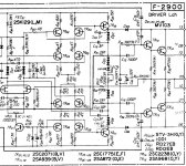
What I chose was Pre drivers: MJE340/350. Drivers 2SA1668 and 2SC4382.
Outputs MJ21193/94.
Initial results were high notch distortion at lower power levels (2.4% THD with 0.5 vrms sine wave out. I spent a few hours revamping the bias circuit to get rid of the notch, but the maximum output is still only about 34 vrms as compared to 42 vrms for the original channel.
Since I selected matched parts for the drivers/pre drivers, the best match was in the lower part of the hfe range. I had some parts in the P junction that were high hfe on the curve tracer, but no N junction devices that would match, so I ended up using low hfe devices throughout the driver PCB.
I called the customer today and discussed the many problems and that the cost of fixing this right is going to be way past his original $300-500 budget. The problems extend to shorted caps in the tuner, bad relays throughout preamp and power amp, bad fan thermostat, dirty controls and a dirty step attenuator (volume). We managed to up the repair budget to $1400, though now customer is demanding the unit be perfect for that money. Thus, I must solve how to get 100 more watts out of the left channel. I'm currently getting about 136 watts into 8 ohms at clipping. Rails are 83 volts.
My hunch is the low hfe devices are preventing enough drive to the output stage. Possibly the original RET outputs had more gain. Many amplifiers have bigger rails for the drivers than the outputs to enable proper drive of outputs, but this amplifier has the same rail potential on both, so that may be a factor. The amplifier operates nicely, other than the lower power output in the rebuilt channel.
The remaining other issues is finding replacements for the relays that mute the power meters and mute the preamp output. They are sealed. The speaker relays are bad, too, but I might be able to remove them, disassemble and clean the contacts.
Any leads on where to get the same or equivalent relays would be a help, too. Thanks!
I've been tasked with the nightmare of rebuilding one of these. Originally, the customer didn't want to spend much to fix it, because he paid near 2 grand for it non-working. I took it on because I'd worked on several other Sansui receivers for him and they were relatively easy to repair.
This G22000 has numerous issues, including bad capacitors in the tuner, bad relays throughout and the main one, blown output and driver stages.
As these parts were no longer available, I spent many hours researching cross referenced parts.
What I chose was Pre drivers: MJE340/350. Drivers 2SA1668 and 2SC4382.
Outputs MJ21193/94.
Initial results were high notch distortion at lower power levels (2.4% THD with 0.5 vrms sine wave out. I spent a few hours revamping the bias circuit to get rid of the notch, but the maximum output is still only about 34 vrms as compared to 42 vrms for the original channel.
Since I selected matched parts for the drivers/pre drivers, the best match was in the lower part of the hfe range. I had some parts in the P junction that were high hfe on the curve tracer, but no N junction devices that would match, so I ended up using low hfe devices throughout the driver PCB.
I called the customer today and discussed the many problems and that the cost of fixing this right is going to be way past his original $300-500 budget. The problems extend to shorted caps in the tuner, bad relays throughout preamp and power amp, bad fan thermostat, dirty controls and a dirty step attenuator (volume). We managed to up the repair budget to $1400, though now customer is demanding the unit be perfect for that money. Thus, I must solve how to get 100 more watts out of the left channel. I'm currently getting about 136 watts into 8 ohms at clipping. Rails are 83 volts.
My hunch is the low hfe devices are preventing enough drive to the output stage. Possibly the original RET outputs had more gain. Many amplifiers have bigger rails for the drivers than the outputs to enable proper drive of outputs, but this amplifier has the same rail potential on both, so that may be a factor. The amplifier operates nicely, other than the lower power output in the rebuilt channel.
The remaining other issues is finding replacements for the relays that mute the power meters and mute the preamp output. They are sealed. The speaker relays are bad, too, but I might be able to remove them, disassemble and clean the contacts.
Any leads on where to get the same or equivalent relays would be a help, too. Thanks!
Attachments
D03, D04, D07, D08 seem to be VD types... What do you mean by revamp bias circuit? Did you check the emitter resistors?
Last edited:
Output stage has been completely rebuilt. Emitter resistors all good.
The existing design didn't turn on the output stage for proper class AB operation. It was operating class B with a notch. I replaced the diodes with triple 1N4148 arrays, but to no avail. The next thing I did was increase the bias voltage by increasing the string potential around the bias pot. That got me enough bias current to eliminate the notch. However, it didn't help with the premature clipping.
What I suspect here is that the original Sanken RET devices in the output had more gain and could be driven fully by this driver circuit. Since replacing them with the OnSemi parts, it works, but there doesn't seem to be enough drive.
Every resistor and diode on the driver board has been tested and found to be within 2% of the marked value.
I'm thinking this may be a matter of hfe being too low on these devices. I've got 19 hours into this problem so far. And there are several more hours worth of work to be done on the preamp/tuner section. Essentially, the whole thing is getting recapped. The four main filter caps are going to cost a lot. As are replacing all of the relays. There are many relays in both sections of this receiver. The small oval green ones seem to be an odd duck. Need to find an equivalent for those.
But the most worrisome matter is why there isn't sufficient drive to run the output stage at full power.
I assume you get the full (voltage) output under light loading ?
From all your descriptions it does sound as if the substituted devices are not suitable (forward gain to low, differing Vbe characteristics etc).
The 2SA1209/2SC2911 come to mind as a possible for the pre drivers.
From all your descriptions it does sound as if the substituted devices are not suitable (forward gain to low, differing Vbe characteristics etc).
The 2SA1209/2SC2911 come to mind as a possible for the pre drivers.
I don't think mje340/50 are at all suitable. Look at Fairchild parts for better replacements. You need to replace all relays, finding suitable parts is not difficult and they are cheap. Cleaning is not an option.
Did you try swapping driver boards?
Driver boards are unique for left and right and labeled as such. Probably not a good idea to attempt.
Thanks for the transistor tips. I'll check availability.
The omron relays could be taken apart and cleaned, but the little green ones are molded.
I assume you get the full (voltage) output under light loading ?
From all your descriptions it does sound as if the substituted devices are not suitable (forward gain to low, differing Vbe characteristics etc).
The 2SA1209/2SC2911 come to mind as a possible for the pre drivers.
I see the hfe is much higher, but the breakdown voltage is low and so is the current capability. 500mA for the MJE part.. 140mA for this part. These two specs have disqualified many alternatives that I looked at.
The MJE340/350 have been fine in everything I have used them in. I don't think they are the issue, but I could be wrong. Verify high voltage to the amp board? Stay correct when driven?
If you have verified all of this, then I would try different predrivers and drivers...
If you have verified all of this, then I would try different predrivers and drivers...
I see the hfe is much higher, but the breakdown voltage is low and so is the current capability. 500mA for the MJE part.. 140mA for this part. These two specs have disqualified many alternatives that I looked at.
Fair point. I must admit I'm a little surprised (looking at the circuit) that it would struggle to achieve full output given that it has pre-drivers > driver and then multiple output pairs.
Are you measuring this 34 vrms vs 42vrms into an 8 ohm resistive load ? If so, does the value increase as the load impedance is raised ?
Check voltage swing at the Vas stage. Unless it is one of those OPS with voltage gain, you should have full swing at the Vas. Someone with a schematic can tell you this.
I'm going to replace the 8 ohm dummy load with something much higher, perhaps 30 ohms, and look at the voltage swing on the output as it approaches clipping. If it's much higher, I'll look at the rails under an 8 ohm load and see what they're doing. I can't rule out high ESR on the PSU capacitors, even though I don't see much rippled during the clipping phase of the waveform.
If you look at the schematic of the driver, you'll see a central line that provides feedback for the whole thing. The voltage will be the same, as this is connected to the zobel network. This circuit uses VBE multipliers with four transistors per half, which is somewhat unique to the Diamond Differential.
I've got several other pieces that just came into the shop, so I'll be rotating among working on all of them. Thus I might take a week to update status on this Sansui.
I'm also looking for a drop in replacement for Sansui reed relay PN. 1150430. Any leads, or at least a spec on the field coil voltage?
Minor update:
I put a 250 ohm resistor across the output of the repaired channel and brought up a 1KHz sinewave. Clipping occurs at 43.5 vrms. So the amplifier is sagging under load. Now I must determine the reason.
I put a 250 ohm resistor across the output of the repaired channel and brought up a 1KHz sinewave. Clipping occurs at 43.5 vrms. So the amplifier is sagging under load. Now I must determine the reason.
Nice work... There is a supply board for each channel. I would look there for the collateral damage. There are also a couple fuse resistors in there you might replace.
As to the Reed Relay, determine the coil voltage and you will likely have to find something that will work (dpst?) and lay it in there dead bug style and wire it up.
Just replace the speaker/protect relays. I think there are some 4 pole relays and some 2 pole relays. Omron MY4-02-DC24, Omron LY2-0-DC24
You can get these about anywhere. Digikey, Mouser, Online Components, etc...
Last edited:
I noticed the rails for the driver board are 79.5 VDC, so I thought "schematic says 86 VDC and checked the original channel. Same voltages there. So the supply is good, and it only sags a few hundred millivolts when the amp is driven to clipping into 8 ohm load.
The emitter resistors are all good, so I'm left wondering if modern OnSemi devices are THAT inferior to the originals..
I traced the drive source for the reed relay and the schematic calls out 33.4V at the transistor that drives it (through another relay contact) and then it passes through a 330 ohm resistor, so I would suspect the relay, if we're talking standard parts here, is probably a 24V coil. The trick is finding one that has the odd pinout configuration, else I have to kluge a modern stock relay to fit this application.
The emitter resistors are all good, so I'm left wondering if modern OnSemi devices are THAT inferior to the originals..
Does it clip symmetrically under 8 ohm load ?
I can't see the outputs being inferior gain wise although early power devices were generally pretty poor in that regard. The same can't be said for some of the small signal parts though.
Are you sure the drivers and pre drivers are OK and fitted correctly. I know that's an odd thing to suggest, but with essentially two drivers forming a darlington it would still all work if one of the pair just had continuity or 'diode continuity' from B to E.
- Status
- Not open for further replies.
- Home
- Amplifiers
- Solid State
- Sansui G22000 with Updated Transistors/Low Power Output