Why not swap predrivers channel to channel?
Because if anything blows up, I'll have TWO channels to repair. 😱
Here's an update on the power output investigation.
I bought three batches of MJE340/350 parts from three different manufacturers. I matched up sets of high hfe parts. These are more than double the hfe of the parts I originally installed, due to finding matching sets only in the low hfe with existing stock.
Replaced TR12,13 with the high hfe parts. Tested power at clipping. No improvement noted.
Measured voltage at base of TR14 and TR15 under full power conditions. Found 40 VRMS on both bases, while output stage was swinging 36 VRMS at the onset of clipping. I could see the clipping in both locations occuring at the same drive level. So the base signal begins to clip in synch with the output signal clipping.
The emitters of TR14,15 swing about 38 VRMS where the outputs clip at 36 VRMS.
After recapping the driver boards, and the power supply main PCB, there was no improvement in performance.
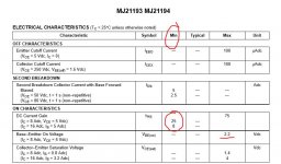
All evidence seems to point to the MJ21193/94 parts being incapable of either sufficient gain or current delivery. I'd say the latter, because with a 250 ohm load, it has no trouble swinging 42 or more volts.
I bought three batches of MJE340/350 parts from three different manufacturers. I matched up sets of high hfe parts. These are more than double the hfe of the parts I originally installed, due to finding matching sets only in the low hfe with existing stock.
Replaced TR12,13 with the high hfe parts. Tested power at clipping. No improvement noted.
Measured voltage at base of TR14 and TR15 under full power conditions. Found 40 VRMS on both bases, while output stage was swinging 36 VRMS at the onset of clipping. I could see the clipping in both locations occuring at the same drive level. So the base signal begins to clip in synch with the output signal clipping.
The emitters of TR14,15 swing about 38 VRMS where the outputs clip at 36 VRMS.
After recapping the driver boards, and the power supply main PCB, there was no improvement in performance.
All evidence seems to point to the MJ21193/94 parts being incapable of either sufficient gain or current delivery. I'd say the latter, because with a 250 ohm load, it has no trouble swinging 42 or more volts.
If you deliberately over bias the amp (say 500ma per pair, 1.5 amps total) and then measure the volt drop across one of the 4.7 ohm base feed resistors you should be able to get an idea of the gain of these 21193/4's.
It might be worth comparing a similar test on the other channel.
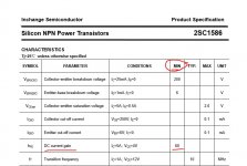
I've just pulled a data sheet on the original output devices and they do seem to be unusually high gain devices... and yet its hard to believe they could be the culprit. The maximum base turn on volts is also rather high although that is specified at very high collector current. Odd !
It might be worth comparing a similar test on the other channel.
I've just pulled a data sheet on the original output devices and they do seem to be unusually high gain devices... and yet its hard to believe they could be the culprit. The maximum base turn on volts is also rather high although that is specified at very high collector current. Odd !
Attachments
I would seem that perhaps I should have selected the output devices for maximum hfe. I only had 8 pieces left in stock, three matched of each type though.
Without actually testing the amp its hard to say. I'm struggling to believe that low hfe would cause this, at least not when you have a driver and pre-driver in front.
Am I imagining this or did you mention earlier on that you had to alter the bias network in order to get the standing current to adjust correctly ?
It might be worth you measuring the voltage across the emitter resistors of TR10 and TR11 and making sure that the VAS stage has enough current capability. Compare with the good channel. I assume the resistors are OK and haven't had something like 1k5 fitted in place of 150 ohm.
Me too. It's the most peculiar thing.
The observable fact is that the output stage is load sensitive. It can swing full 42 volts with a light 250 ohm load, but not with an 8 ohm load. The inability to sink current would seem to be a power transistor issue, rather than a driver issue.
I'll check those emitter resistors. Maybe do a side by side ohmmeter check (again).. the last time I did one, both boards' resistors measured identical.
Another thought and something that's easy to try. Those 4.7 ohm base feed resistors. If you drop them a little, say to 3.3 ohm, do you then see a rise in available output swing into 8 ohms ?
If the emitter resistors had gone high it would give this fault but I thought we checked those way back.
If the emitter resistors had gone high it would give this fault but I thought we checked those way back.
I triple checked the resistance of the emitter resistors for TR10 and 11 and they are 149 and 150 ohms, actual reading.
All output transistors were pre selected on a curve tracer before installation, so yes, they are working. All emitter resistors read within 2% of 0.33 ohms. All base drive resistors are close to 4.7 ohms. But yes, the notch and the apparent high output impedance seems awfully like missing output devices.
I'm in the process of replacing the main power supply filter caps, which came in this week. Getting at any of those resistors on the heat sink involves removing the heat sink cover again and then unbolting the heat sink. I had one more round with the cover today as I pulled two of the outputs to compare them for Gm on the curve tracer against 20 new devices I just received. I also found one of six of the originals that still works and the Gm is about the same for the PNP devices I put in there. So I guess that pretty much settles the question of hfe.
If you can't get to the emitter resistors to measure them while it's running can you get to the base resistors and measure the voltage across them? If an output transistor was out of circuit there would be no base current, correct? This is a strange one and the cure as always will be something very very stupid.
Craig
Craig
All of these resistors are packed between the heat sink and chassis. Operating it with the heat sink dangling on the wiring would be quite risky. But I might try it at some point if all else fails.
Yes, it's got to be something ridiculously basic that's causing this, but so far, all the basics, like checking power rail voltage at the collectors of the output stage, all show full voltage under load. (Actually, supply sag is worse on the 'good' channel.)
That thought keeps kicking around:
It will swing full voltage with little or no load, but a load drags it down a lot. The damping factor probably is very poor, too.
If the good channel is operating correctly then the sag should be worse. That's a good indication that the bad channel isn't pulling as much current, for whatever reason.
As many of the MJ21193/4s I use I've never had a problem like this either on American or Japanese amps.
Craig
As many of the MJ21193/4s I use I've never had a problem like this either on American or Japanese amps.
Craig
The pinout on the replacement drivers differs from the originals, so I did a crossover with teflon tubing to prevent shorts. I can't imagine it working at all if the C-E connections were reversed.
I've used the ON Semi parts in many big Marantz amps and they have always improved the performance. That's why the Sansui's behavior is so perplexing. But then, it's not just the outputs that had to be replaced--the entire driver section, back three levels was shorted and had to be rebuilt.
I've used the ON Semi parts in many big Marantz amps and they have always improved the performance. That's why the Sansui's behavior is so perplexing. But then, it's not just the outputs that had to be replaced--the entire driver section, back three levels was shorted and had to be rebuilt.
Very frustrated now. After replacing the large electrolytic cans on the chassis, I find that the right channel (original, good working channel) does not work now. No problem, I must have left off a connection or a wire broke when I was pushing the board to the side to get to the terminals on the can caps, I thought. But two thorough examinations of the under side of the board and all the connection to the board in the power supply revealed no problems.
So I next entertain the possibility that one of the fuse resistors failed on the driver PCB. Checked all resistors and found them to be good. Then checked transistors. Nothing shorted.
So I check at the Zobel network and find that it goes negative by 0.6 volts when the amp power supply comes up. No signal passing through when a generator is connected.
My intuition is telling me something's not getting power somewhere, but since all connections have been checked and re-fitted, and all fuses check good, this is a real head-scratcher.
I'm already 7-1/2 hours over budget on the repair of this unit and now the 'good' channel has stopped working. I have to put this aside for a few weeks and 'cool off'. Maybe come back to it in the fall.
A random transistor failure in the power supply for the driver PCB. TR02, which is the drive half of a Darlington arrangement, went open from C-E. And it's not in a particularly stressed function, being it's not a pass transistor. It just provides voltage reference to the base of the pass transistor. So I replaced it with MJE340 and it seems to be working now.
This amplifier is full of ticking time bombs. Who knows what else will fail when the customer gets it home.
This amplifier is full of ticking time bombs. Who knows what else will fail when the customer gets it home.
Why do you use MJE parts when Fairchild has excellent equivalents to almost all old japanese transistors? They're cheap, too.
Am I imagining this or did you mention earlier on that you had to alter the bias network in order to get the standing current to adjust correctly ?
It might be worth you measuring the voltage across the emitter resistors of TR10 and TR11 and making sure that the VAS stage has enough current capability. Compare with the good channel. I assume the resistors are OK and haven't had something like 1k5 fitted in place of 150 ohm.
Yes, I did modify the bias network to get rid of the notch at zero crossing.
Here are the measurements across the emitter resistor of TR10:
.752 VDC (idle) .812 VDC (clipping)
Here are the measurements across the emitter resistor of TR11:
.760 VDC (idle) .730 VDC (clipping)
Still scratching my head on this one...
- Status
- Not open for further replies.
- Home
- Amplifiers
- Solid State
- Sansui G22000 with Updated Transistors/Low Power Output