I do know what you say, but what is wrong about asking? this is DIY, yes?
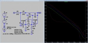
Just for being able to do so, as was said before the loop gain should go down when loading the first amplifier, this little simulation shows the opposite. See also that the phase behavior is not changed for different loads but the open loop gain is.
Sorry that I do not have the correct models, but the simulation is still interesting.
Attachments
While the 211 is good, CMR isn't infinite and there is a bias current slope vs CM-voltage (Fig 19). Performace of the composite is certainly limited by that in non-inverting low-gain/buffer with large input voltage. Input capcitance may vary as well a bit, adding some distortion.e) Is the -180dB number in inverting or non inverting configuration? That is, are the common mode distortions included or not?
Tracking the 211's supplies with the (+)input voltage would help, and while we're at we can freeze the 211 ouput voltage as well so that the master opamp always runs with non-moving input and output voltage and should sport the lowest possible distortion in any config. Except for the tiny corrective signal send to the slave OpAmp the 211's operation point is fully frozen, nothing is moving at all. Output load on 211 is low, so I would think it can't get any better than this.
See attached sketch (will have to try that, actually....)
Attachments

I do know what you say, but what is wrong about asking? this is DIY, yes?
Just for being able to do so, as was said before the loop gain should go down when loading the first amplifier, this little simulation shows the opposite. See also that the phase behavior is not changed for different loads but the open loop gain is.
Sorry that I do not have the correct models, but the simulation is still interesting.
Samuel made the point that the available models are not really sufficient for this kind of deep analysis.
Although your sims don't look unreasonable.
Jan
But alas wouldn't work practically, as separate floating supplies per composite opamp is not exactly cheap or without issues of its own?Tracking the 211's supplies with the (+)input voltage would help
Might be easy to tailor the input opamp to particular requirements of each application - for audio the precise offset voltage isn't needed, but better current noise than the 211 would be great to have for many situations.
I wonder what benefits you can get compositing two much cheaper opamps?
Transient analysis will most likely never work (I did try using the LT1028) but the AC analysis give reasonable results.
As the simulations show, earlier and this one, it is posible to load down the output of the first opamp with limited effects (lets say 10 ohm).
Concluding: If loaded down by 10 ohm, the output current at lock-up or -down (at a vp/vn of 5V) would be 500mA. It is not likely that the opamp will deliver this current and thus lock-up or -down will be prevented (I think).
Result: It should be tested if the diode-network kan be replaced by a 10 ohm resistor from the output of the first opamp to ground (hey it's there!).
Done: Yes I did read the paper, and (from the paper) it seems not that the diode network has (should have) any influence on gain and of phase, allowing it to be replaced by some other solution.
Just posting an idea..
Yes, like a low noice opamp and a high current DSL-amp.
PS: Not cheap but interesting (possibly), I will try to find time for such an experiment (but not at this moment).
As the simulations show, earlier and this one, it is posible to load down the output of the first opamp with limited effects (lets say 10 ohm).
Concluding: If loaded down by 10 ohm, the output current at lock-up or -down (at a vp/vn of 5V) would be 500mA. It is not likely that the opamp will deliver this current and thus lock-up or -down will be prevented (I think).
Result: It should be tested if the diode-network kan be replaced by a 10 ohm resistor from the output of the first opamp to ground (hey it's there!).
Done: Yes I did read the paper, and (from the paper) it seems not that the diode network has (should have) any influence on gain and of phase, allowing it to be replaced by some other solution.
Just posting an idea..
… I wonder what benefits you can get compositing two much cheaper opamps?
Yes, like a low noice opamp and a high current DSL-amp.
PS: Not cheap but interesting (possibly), I will try to find time for such an experiment (but not at this moment).
The rail tracker can be quite simple in this case, we only need a few volts of supply at quiescent current levels. Two capacitors, basically (or Zeners, or simple local shunts). See (PDF) Supply bootstrapping reduces distortion in op-amp circuits for example.But alas wouldn't work practically, as separate floating supplies per composite opamp is not exactly cheap or without issues of its own?
When we aim at this level of performance a slightly more complex supply is irrelevant for the total effort (Layout etc). It also makes little sense to use lesser opamps. The exception being to make a lowest-cost mass-market commercial design...
Last edited:
I think these types of op amps are interesting for audio analyzers. These are not useful for normal DIY audio applications because they are too complex and expensive. In a complete preamplifier you have at least 20 or 30 op amps. Nevertheless an interesting project.
In a line level amp I don't see any more than one to four stages max (see B.Putzey's PreAmp). Add another for Phono, and another for a dedicated headphone drive. When you need 10++ stages per channel something is wrong in the design...I think these types of op amps are interesting for audio analyzers. These are not useful for normal DIY audio applications because they are too complex and expensive. In a complete preamplifier you have at least 20 or 30 op amps. Nevertheless an interesting project.
When you need 10++ stages per channel something is wrong in the design...
Or you are doing things that others don't, albeit in many cases things that DSP can do a lot more easily 🙂
Here is a complete preamplifier, the NS10 by Threshold, circa 1978. Circuit designed by Nelson Pass.In a complete preamplifier you have at least 20 or 30 op amps. Nevertheless an interesting project.
Because he included DC servos to minimize offset voltage, there are two opamps inside each can. One for the forward path (signal), another to set the DC bias (servo).
Phonostages on the left, line amps on the right.
_
Attachments

Only V(out8) has it's loop-gain changed by loading (it seems). When studying it better you will realize that the lowered output voltage is due to the output impedance of the amplifier.
What is the supposed relation between the closed-loop gains of these simple single-op-amp circuits and the loopgain of Groner's composite op-amp?
That is, when you load the output of U1 in the picture in the opening post with a resistance that is small compared to the open-loop output impedance, it is quite clear that the gain from input to output will drop.
The circuit in the opening post is meant to be used in a conditionally stable feedback loop. Reduce loopgain in a conditionally stable loop and its stability will degrade until it eventually starts oscillating, at least when the open-loop pole and zero positions don't change (as you can easily test with the attached circuit).
It is unclear to me what the circuits in posts 63 and 64 have to do with this. I think you only demonstrate that you can reduce the load resistance of a closed-loop unconditionally stable op-amp amplifier a lot before the low-frequency closed-loop gain drops. As far as I'm concerned, that was already perfectly clear before you demonstrated it.
Attachments
While the 211 is good, CMR isn't infinite and there is a bias current slope vs CM-voltage (Fig 19). Performace of the composite is certainly limited by that in non-inverting low-gain/buffer with large input voltage. Input capcitance may vary as well a bit, adding some distortion.
Tracking the 211's supplies with the (+)input voltage would help, and while we're at we can freeze the 211 ouput voltage as well so that the master opamp always runs with non-moving input and output voltage and should sport the lowest possible distortion in any config. Except for the tiny corrective signal send to the slave OpAmp the 211's operation point is fully frozen, nothing is moving at all. Output load on 211 is low, so I would think it can't get any better than this.
See attached sketch (will have to try that, actually....)
Supply Bootstrapping Reduces Distortion In Op-Amp Circuits | New operational amplifiers optimized for high-performance audio and ultrasound applications combine extremely low total harmonic distortion plus noise (THD+N), -130 dB, with large output voltage | Electronic Design
Our own Dimitri wrote this; I think there's other places on the internet that have copies with the figures. Very close to what you're proposing, albeit he used a unity buffer for the output opamp.
Yep. I gave a link to a complete PDF in #72.
My proposal in #67 differs in that the tracking source is the input signal, not the output signal. If we only want to track the rails output as source is OK, but to avoid output voltage swing of the control amp (which may cause additional distortion) we must use the input signal to force the slave amp (-)Input voltage which defines master amp output voltage. We can't use a divider from the output for this as this would take down the slave gain, now running in low fixed gain hookup.
As mentioned, the idea is to lock down the master opamp's input and output voltages to zero (AC) in any circuit config so that the only fluctation seen is the tiny voltage to drive the (quasi open-loop) slave amp. The master amp always works under inverting operating conditions. An inverting mode emulator of sorts.
Last edited:
What is the supposed relation between the closed-loop gains of these simple single-op-amp circuits and the loopgain of Groner's composite op-amp?
Simple, the loading changes the GBW and that changes the loop gain at high frequencies and that may need changes in the components used to stabilize the circuit. The sims show GBW changes as predicted and indicate near to no phase changes. To me it seems (likely) posible to load the first amplifier (with a 10 Ohm or there about resistor), and then remove the diode's network (but I am not 100% sure), it is worth a test because it simplifies the circuit, makes the used copper area smaller (removing som capacitive and inductive influences) etc.
Last edited:
My experience with composites is that you always need a secondary path for the master amp feedback to remain closed when the slave amp saturates. Loading down the master does nothing in that regard, exactly the opposite actually, driving the master into current limit when the loop opens. Recovery from overdrive will be horrid.
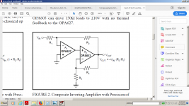
The diode T-network accomplishes the trick in the best possible way, it closes the loop under overdrive but does zero harm in normal operation. The bleeder R is essential, of course. The T-network is a classic clamp circuit used successfully for ages, for single stages (see OPA627 datasheet) and for composites.
...and I might add my proposed bootstrapping scheme will allow for the T-clamp in non-inverting config as well.
I was not competing, it was just to prevent the lock up's/down's that my idea took hold. If there are other concerns that need the diode's network then a single resistor loading of the amplifier may not work, but still I wonder, is it not worth to do the test?
When the input is high enough to cause significant common mode distortions might be more practical to go inverting topology....and I might add my proposed bootstrapping scheme will allow for the T-clamp in non-inverting config as well.
Attachments
I was not competing, it was just to prevent the lock up's/down's that my idea took hold. If there are other concerns that need the diode's network then a single resistor loading of the amplifier may not work, but still I wonder, is it not worth to do the test?
In my implementation, without the T-diode clamp, the system went into a sort of squegging mode on the neg. wave part, developing a sawtooth riding on the neg sine, a few 10's of kHz. Sorry, didn't save the pic.
Jan
- Home
- Source & Line
- Analog Line Level
- Samuel Groner's super opamp