Hello
I have some BT module, what output has i2s.
I need right justified, so i will use for it CS8421
But other problem is, that this module has HFP, and sampling for it is low (8k WS and 512K clock).
This CS8421 going to unlock state, when HFP is on.
I like to use before CS8421 AK4121 to up convert to min 44.1K sampling.
I know, that all will be up or down to 44.1k, but this way is it possible to connect to dac?
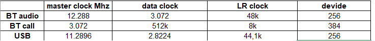
Normal i have 48K WS with 3.07Mhz clock (i thing 20bits), and HFP has 8k/512 (8bits)??
Is this AK4121 should up/down varius sampling to one?
I have some BT module, what output has i2s.
I need right justified, so i will use for it CS8421
But other problem is, that this module has HFP, and sampling for it is low (8k WS and 512K clock).
This CS8421 going to unlock state, when HFP is on.
I like to use before CS8421 AK4121 to up convert to min 44.1K sampling.
I know, that all will be up or down to 44.1k, but this way is it possible to connect to dac?
Normal i have 48K WS with 3.07Mhz clock (i thing 20bits), and HFP has 8k/512 (8bits)??
Is this AK4121 should up/down varius sampling to one?
If you have a 3.07MHz master clock (should actually be 3.072MHz), from the table at: https://en.wikipedia.org/wiki/Crystal_oscillator_frequencies ...To generate 48kHz would require 64fso. However AK4121 data sheet, Table 1, shows a minimum output setting of 256fso. Therefore it appears you would need a higher frequency master clock. If you then wanted to run CS8421 from a lower frequency clock, you could use a clock divider chip to divide the master clock down to the frequency you would prefer. That way AK4121 I2S output should be synchronous with CS8421 master clock.
The other thing is that AK4121 supports only down to 16-bits. If HFP mode uses less than 16-bits, then 8-bit data would seem to require some zeros appended to the LSB end of the data so there are effectively 16-bits. It also means the I2S input bit clock frequency, BCLK, would need to be for a 16-bit word size.
Okay. That's my quick opinion from briefly looking at datasheets. Not sure if I missed anything that might be important. Maybe someone else has some other ideas.
Last edited:
No, you have not missed anything 😉That's my quick opinion from briefly looking at datasheets. Not sure if I missed anything that might be important.
hi, so this chip is not for my device, what will be better?
i just looked to input/output, and i hope that will be ok.
i just looked to input/output, and i hope that will be ok.
I can not change anything on i2s master chip, so any changes master-clockn is not possible, i do not have this signal on bt.If you have a 3.07MHz master clock (should actually be 3.072MHz), from the table at: https://en.wikipedia.org/wiki/Crystal_oscillator_frequencies ...To generate 48kHz would require 64fso. However AK4121 data sheet, Table 1, shows a minimum output setting of 256fso. Therefore it appears you would need a higher frequency master clock. If you then wanted to run CS8421 from a lower frequency clock, you could use a clock divider chip to divide the master clock down to the frequency you would prefer. That way AK4121 I2S output should be synchronous with CS8421 master clock.
The other thing is that AK4121 supports only down to 16-bits. If HFP mode uses less than 16-bits, then 8-bit data would seem to require some zeros appended to the LSB end of the data so there are effectively 16-bits. It also means the I2S input bit clock frequency, BCLK, would need to be for a 16-bit word size.
Okay. That's my quick opinion from briefly looking at datasheets. Not sure if I missed anything that might be important. Maybe someone else has some other ideas.
Clock is depend of source of streaming, BT has 3.07M, usb has 2.82M..it is look like BT has 96k and usb from 44.1k.
How to do this?
Sorry, i checked it and i have master clock from chip, 11.285M, so it can be useI can not change anything on i2s master chip, so any changes master-clockn is not possible, i do not have this signal on bt.
Clock is depend of source of streaming, BT has 3.07M, usb has 2.82M..it is look like BT has 96k and usb from 44.1k.
How to do this?
So connect master-clock to data clock input and should works?Looks like AK4121 could output 44.1kHz digital audio, if using an 11.285MHz master clock.
Clock data is to low for it?
No. You have to read the datasheet for AK4121 very carefully until you understand it all. If you need to ask questions about what it says, no problem. Can't design it all for you though. You have to do most of the work.
ok my master clock looks like:
i have to calculate divide..
for BT call i have different divide..
so, when i connect maser clock as data clock and setup divide by 256, it can be work, but what about this different sample on call?
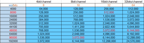
i made some table for master clock and bits/channel
it like is 32/16 bits no less..
So, mode 1 can be set-up to (256fso~96kHz), but to change i need pullup CMODE0 and reset ak4121?
it can be done, i have to look, if i have free gpio...
my player is strange, it is for volvo car, and that is the problem..i can not interfere to boards, only replace data from cd drive..
i have to calculate divide..
for BT call i have different divide..
so, when i connect maser clock as data clock and setup divide by 256, it can be work, but what about this different sample on call?
i made some table for master clock and bits/channel
it like is 32/16 bits no less..
So, mode 1 can be set-up to (256fso~96kHz), but to change i need pullup CMODE0 and reset ak4121?
it can be done, i have to look, if i have free gpio...
my player is strange, it is for volvo car, and that is the problem..i can not interfere to boards, only replace data from cd drive..
Attachments

Last edited:
So, mode 1 can be set-up to (256fso~96kHz), but to change i need pullup CMODE0 and reset ak4121?
Typical for AKM ASRC chips, PDN should be held Low while any CMODE pins are changing state.
However, according to Table 1 of the datasheet:
For Mode 1 operation MLCK must be "384fso (fso~96kHz)."
Whereas Mode 0 is needed for "256fso (fso~96kHz)."
EDIT: Maybe another way to go about figuring out settings is to start with a prospective input sample rate, then examine what settings would be required to produce a useable output sample rate. If such settings appear to exist, then take another look at the datasheet to see if any other device requirements would be violated. Everything in the datasheet could show up some possible issue, including limitations listed in the 'Features' section. Otherwise, you are free to experiment and see what you can get working.
Sometimes there are things not precisely spelled out in datasheets. For example, AK4137 looks like it should be able to upsample from 16/44 to 24/192 and convert from PCM to DSD256 all at the same time. If you try it, turns out that it seems to work. However, in the 'Examples' section of the datasheet that particular conversion combination is not listed. Further experimentation shows that SQ is not very good with that particular combination, so it is not listed as an 'Example.' What people have discovered is that it takes two chips to do the job right, one to do the upsampling, and the second chip to do the DSD conversion. Of course, maybe the problem will be fixed in the next version of AK4137, which AKM is planning to develop.
Last edited:
For DACs and cables, that would depend on the type of experimentation, not the price or bling factor. Posting the details of such experimentation would help the discussion.Further experimentation shows that SQ is not very good with that particular combination,
My next step is connect master-clock to data-clock and i will try setup 256.
If this will work, i have free one gpio to use for reset (esp8622), so i can reset ak chip when call mode is on.
I give some info about progress.
If this will work, i have free one gpio to use for reset (esp8622), so i can reset ak chip when call mode is on.
I give some info about progress.
Then what was that "SQ is not very good with that particular combination" evaluated on?is neither dac nor cable.
PLL loop filter should be as suggested in Figure 7. Small value caps should probably be C0G/NPO or film. Larger value caps should probably be aluminum electrolytic (or else maybe small physical size yet reasonably good linearity film, such as Wima MKS2 series). Resistors should be metal film. Keep the components close to the pin to help minimize noise pickup.
Can any answer, what is PLL Loop-Filter?
What frequency should be on this pin?
Essentially 0 Hz, as it should be a DC voltage with a very small ripple on top.
No pullup is needed. AK4121 outputs should probably have small physical size, roughly 33-ohm resistor in series (see attached image). The resistors should be located very close to the AK4121 output pins. What is coming out is RF so care needs to be taken to route it accordingly.
The 50-ohm transmission line in the image (sort of looks like a 50-ohm coax), is another thing to understand. https://www.allaboutcircuits.com/te...-life-rf-signals/what-is-a-transmission-line/
The 50-ohm transmission line in the image (sort of looks like a 50-ohm coax), is another thing to understand. https://www.allaboutcircuits.com/te...-life-rf-signals/what-is-a-transmission-line/
Attachments

- Home
- Source & Line
- Digital Source
- sample conventer issue