I am trying to fix the US amp Merlin md3d amplifier that I believe it to be a Class A B. If I put one Probe on either the B+ and then the other probe anywhere else in the board it measures 12 volts. if I take that probe off and put it on the remote terminal the same thing occurs...... 12 volts everywhere. if I switch the probes in the opposite direction it shows negative 12 volts. I do not remember getting any other voltage reading other than 12 volts. anywhere I measure whether it be the power transistors, either side of the Transformers, all three legs of the transistors, i mean everywhere 12 volts. ...everywhere.
Hi Blindcracker,
I'll assume the amp is not working or powering up. Sounds like it is open in both B+ lines, your trigger line should measure positive wrt ground. Does it?
I'll assume the amp is not working or powering up. Sounds like it is open in both B+ lines, your trigger line should measure positive wrt ground. Does it?
He's measuring +12 with the + lead on the B+ lines, and browsing with his negative lead. That means absolutely everything else is at ground potential. An open ground would give him zero volt readings everywhere as everything would drift high.
I asked about ground to trigger (in the triggered state) to ensure he was measuring correctly.
I asked about ground to trigger (in the triggered state) to ensure he was measuring correctly.

Yes I noticed the B+ thing just after I posted, so I deleted my post. It sounds like the amp isn't powering up at all.
No, no signs of life. What is this trigger line you speak of? Maybe you're talking about a scope.i have one but I only used a multimeter.
Just to be clear I will put the red probe on B plus and use the black lead to take measurements and everything I touch with it is 12 volts. EVERYTHING!!!! GATE RESISTORS, CURRENT SENSEING RESISTORS, EVERY SINGLE WINDING ON THE TRANSFORMER, ALL THREE LEGS ON THE POWER AND OUTPUT TRANSISRORS, THE RECTIFIERRS, PROTECTION DIODES . All 12 volts. I bet you'll never guess what I measured on All 18 PINS OF THE 494 DRIVER CHIP. THEN I SWITCH THE LEADS AROUND and everything now reads negative 12 volts. Then I repeated thr exact same process but instead of using b+ I use the remote terminal and it is again 12 volts and negative 12 volts.
The way you are measuring is actually not very useful at all. All the meter is telling you is that the amplifier is off.
From what you're describing it sounds like the power supply is dead. Start with the basics. With the black probe on ground, are you getting 12V out of the fuses?
From what you're describing it sounds like the power supply is dead. Start with the basics. With the black probe on ground, are you getting 12V out of the fuses?
Hi Blindcracker,
A car amplifier has a lead that tells it to turn on. Historically called "trigger", basically you put your B+ on that to tell the amp your car radio is on and to power up. Otherwise the amp would run all the time and kill the battery.
So start with the basics. I don't think you have any experience in service so just slow down and we'll take things step by step. Meter neg on ground, positive probe on your remote lead in. If it isn't at B+, your amp will not turn on. Simple.
With the black probe On The Ground Terminal using a computer power supply I get 11.77 volts when I put the red probe on either the B+ terminal or the remote terminal. There are six fuses and leading the probe On The Ground Terminal and placing the red Probe on all six fuses one at a time delivers zero volts. Although I wasn't asked to out of curiosity I placed the red probe on the B+ terminal and the black Probe on the fuse and I get 11.77 volts and I get the same if I put the red probe on the remote and keep the black Probe on the fuses.
Sorry but WRONG measuring process.I am trying to fix the US amp Merlin md3d amplifier that I believe it to be a Class A B. If I put one Probe on either the B+ and then the other probe anywhere else in the board it measures 12 volts. if I take that probe off and put it on the remote terminal the same thing occurs...... 12 volts everywhere. if I switch the probes in the opposite direction it shows negative 12 volts. I do not remember getting any other voltage reading other than 12 volts. anywhere I measure whether it be the power transistors, either side of the Transformers, all three legs of the transistors, i mean everywhere 12 volts. ...everywhere.
Put black probe on ground/chassis/- terminal (all 3 are the same) and measure everywhere else with the red probe.
Your "12V everywhere" actually means "ZERO Volts everywhere" , also called: "unpowered amplifier"
Again: WRONG measurement.Just to be clear I will put the red probe on B plus and use the black lead to take measurements and everything I touch with it is 12 volts. EVERYTHING!!!! GATE RESISTORS, CURRENT SENSEING RESISTORS, EVERY SINGLE WINDING ON THE TRANSFORMER, ALL THREE LEGS ON THE POWER AND OUTPUT TRANSISRORS, THE RECTIFIERRS, PROTECTION DIODES . All 12 volts. I bet you'll never guess what I measured on All 18 PINS OF THE 494 DRIVER CHIP. THEN I SWITCH THE LEADS AROUND and everything now reads negative 12 volts. Then I repeated thr exact same process but instead of using b+ I use the remote terminal and it is again 12 volts and negative 12 volts.
They are not even getting supply voltage since each measures 0V on both ends.Are the fuses blown?
I guess there is a main beefy relay connecting supply to all the rest of the amp and it is not being activated/triggered.
There may be one large "main" fuse protecting the whole amp, in that case at least "one* fuse should show 12V on one terminal, 0V on the other.
Please recheck all fuses, fuse holders, etc. for that but ALWAYS with black probe on chassis/ground.
Any other measurement only adds confusion.
Hi Blindcracker,
C*r*a*p, do not use a computer power supply! Use a car battery if you must, but a 12 to 14 VDC regulated power supply is best. 4~5 amps should be good enough to fire most amps up, you'll need 15 ~ 25 amperes to run a car amp up high. More for the really big ones.
Computer power supplies for 12 V don't deliver that much power - and it is noisy as heck. A very bad idea.
On most car amps the fuses are on the main 12V feed so they are usually live all the time. They are normally parallel to each other in circuit. The remote trigger usually switches on the SMPS, no relay involved. I suggested he post some pictures so we can verify this.They are not even getting supply voltage since each measures 0V on both ends.
I guess there is a main beefy relay connecting supply to all the rest of the amp and it is not being activated/triggered.
There may be one large "main" fuse protecting the whole amp, in that case at least "one* fuse should show 12V on one terminal, 0V on the other.
Please recheck all fuses, fuse holders, etc. for that but ALWAYS with black probe on chassis/ground.
Any other measurement only adds confusion.
If I need To take better pictures or get a closer up Shot just let me know
Attachments
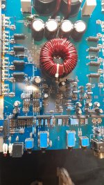
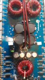
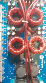
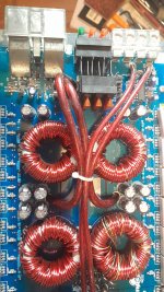
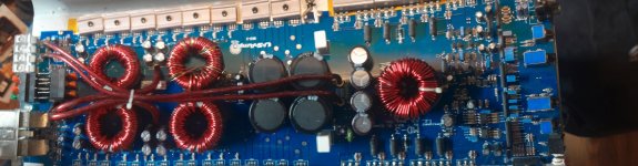
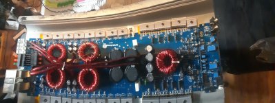
I see nothing that looks like what I would call a relay in this amp. I apply 12 volts to the amp tested all six fuses they already had zero volts I took all six of them out of the circuit check them with the continuity meter and they all were good
Ok, then if no relay involved (which would be the old style solution) then probably, as suggested above, the SMPS converting +12V from battery into needed power amp rails (think +/-35V or so) is not being turned on.
Which is an obscure, complex problem well beyond what can be solved through a Forum, sorry.
At least without a Service Manual or at least a schematic.
I still expect to find at least one fuse in the main +12V line.
It would be the one with the highest current rating.
Doesn't the amplifier have a terminal called "remote" or similar?
- Home
- Amplifiers
- Solid State
- Same voltage everywhere