Do you have any desoldering braid (used braid is perfectly fine)?
If not, wire will be used to bridge the gap.
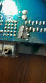
You will need to scrape the blue solder mask off and clean all copper to bright shiny condition. Then you will bridge it with copper wire or braid.
There may be other problems that you need to check for, first. There are two large diodes near the B+ and ground terminals (designated as D7 and D8, marked 6A10?). What resistance do you read across those two diodes?
If not, wire will be used to bridge the gap.
You will need to scrape the blue solder mask off and clean all copper to bright shiny condition. Then you will bridge it with copper wire or braid.
There may be other problems that you need to check for, first. There are two large diodes near the B+ and ground terminals (designated as D7 and D8, marked 6A10?). What resistance do you read across those two diodes?

I do some braid. As far as the diodes go, it'll have to wait till I'm off from work at 7 in the morning but I will do it.
Fuses in parallel, same as diodes in parallel, are poor Engineering to put it mildly."I still can't believe there is not some kind of fuse in the +12V feed line between a HIGH CURRENT source such as a large car battery and this 2 kW amplifier +12V main supply terminal.
I expect a >200A one, go figure."
The six fuses are in the 12V feed. They will be paralleled to handle the current.
Zero guarantee they will share current evenly.
The weaker one will blow first and then the others will cascade like firecrackers. Bad idea.
Now if each one feeds a different load, that's different and justified.
In any case, none is getting +12V from battery, so until that is solved, this is just an idle discussion.
What I suspected.I do believe we have found the problem. What circumstances would have made this possible and what is the best option available to me in order to fix It?
To confirm: +12V should reach one side of that breach.
Regarding the comment on the fuses, That's how it's done. If all of the fuses are the same, if one opens, current flow is enough for all to open. The current sharing is close enough.
From what I see, it's a 50w iron which will be borderline to heat the terminals on the 12v terminal. Solder the braid the full width and length of the copper from the fuse holders and spread it wide along the copper on the terminal side. Fill it well with solder. But first, check the diodes.
When/how did the amp stop working?
I do not know too much about the amp's demise. Dude brought it to me saying another dude had brought it to him. Dude said that dude had told him that the amp work just fine until he let some other dude borrow it . Upon the return of the amp from dude back to dude dude clsimed that it no longer was working so he just gave it to the dude that gave it to me.
Dude!!!!!!!! Don't worry. I will do as you say and check the diodes first.
Dude!!!!!!!! Don't worry. I will do as you say and check the diodes first.
I agree, it is poor engineering, but standard ATC automotive fuses come in 40A maximum rating. Maxi or Mega fuses would be a better choice but I've never seem them used in a car stereo.Fuses in parallel, same as diodes in parallel, are poor Engineering to put it mildly.
Zero guarantee they will share current evenly.
The weaker one will blow first and then the others will cascade like firecrackers. Bad idea.
Now if each one feeds a different load, that's different and justified.
In any case, none is getting +12V from battery, so until that is solved, this is just an idle discussion.
You have to remember this is very price conscious consumer electronics. Doing things the correct way as in industry simply won't happen, the product would be too expensive.
So as Perry said, they all do it that way, and they always have. They did it way back when I was servicing car amps. There is no point in griping about it.
I would guess someone reversed power. If you're lucky, the trace acted as a fuse. Desoldering braid is the exact, correct way to repair the damage. Use silicone adhesive or something to stick it down in case it overheats and melts the solder if the same thing happens again.
What do you read across the solder pads for the diodes? If you don't read anything near 0 ohms (preferably see a rising number from caps charging) do as described below.
Solder a temporary wire or braid jumper across the burned trace. You can reinstall the diodes. Install only one 10-15 amp fuse (all other fuse holders empty).
Connect your meter across the output of one of the rectifier diodes (tab of one positive rectifiers) black probe on ground. Connect B+ and ground. If the fuse doesn't blow and no FETs get hot, touch the remote to the positive supply for a few seconds. Does the amp build rail voltage? Or does the fuse blow?
- Home
- Amplifiers
- Solid State
- Same voltage everywhere