I will use 2 50VA 2X9V transformers on mine and should be enough.
Regarding your last question, better ask at the dam 1941 thread.
Regarding your last question, better ask at the dam 1941 thread.
There are 10 R-Core transformers listed at Audiophonics, and quite affordable.
R-CORE transformers - Audiophonics
They come in 30VA and 60VA. Don't know though what quality they are as never purchased one, but a large choice from a usualy reputable shop. Feedback appreciated!
I hope this helps
Claude
R-CORE transformers - Audiophonics
They come in 30VA and 60VA. Don't know though what quality they are as never purchased one, but a large choice from a usualy reputable shop. Feedback appreciated!
I hope this helps
Claude
I will use 2 50VA 2X9V transformers on mine and should be enough.
Regarding your last question, better ask at the dam 1941 thread.
Thanks.
Regarding a separate psu for the display, Soren responded "No, the display is just another digital part."
... which is independent noise source. 😛pp"No, the display is just another digital part."
... which is independent noise source. 😛pp
I am confused. Could you please explain your thinking.
nash
Simplistically each display is row-column type device, where the crossing is one (or more if it is the colour type) "point". Brightens the point must to use some kind of switching device (for example transistor). Each switching generates more or less noise on the power supply.
The display refreshing also generates noise, even more the micro controller/microprocessor, which controls the display.
IMHO not a smart thing using DAC and control/display devices with common DC voltage.
Look my solution:
GB for ArDAM Lite bare PCBs
Each subassembly has own separated PSU.
The control device (ArDAM Lite) output/input is isolated (feed by separated low noise PSU) from the DAC control pins.
Even better...
Just forgo the display altogether, problem solved. Or use a display which is programmed to go to sleep (even the processor) after receiving commands (this is what Ayre does). Otherwise I think at least a separate transformer winding to power the display is in order in a low noise digital/analog environment.
Simplistically each display is row-column type device, where the crossing is one (or more if it is the colour type) "point". Brightens the point must to use some kind of switching device (for example transistor). Each switching generates more or less noise on the power supply.
The display refreshing also generates noise, even more the micro controller/microprocessor, which controls the display.
IMHO not a smart thing using DAC and control/display devices with common DC voltage.
Look my solution:
GB for ArDAM Lite bare PCBs
Each subassembly has own separated PSU.
The control device (ArDAM Lite) output/input is isolated (feed by separated low noise PSU) from the DAC control pins.
Just forgo the display altogether, problem solved. Or use a display which is programmed to go to sleep (even the processor) after receiving commands (this is what Ayre does). Otherwise I think at least a separate transformer winding to power the display is in order in a low noise digital/analog environment.
Hello Salas, is my math correct?
for
26v - 140mA:
2.4 ohm R1
transformer 20vac - 35va
for
8v - 35mA:
4 ohm R1
Transformer 9vac - 10va
for
26v - 140mA:
2.4 ohm R1
transformer 20vac - 35va
for
8v - 35mA:
4 ohm R1
Transformer 9vac - 10va
The resistors for mA needed are enough. The Vac are not enough for at least 5V input to output differences.
Thanks euro21.
Since I am planning on connecting the dam1941 directly to my DCG3bal without its output buffer I would not be needing the volume control or the display but just the buttons and their respective LED's; at least thats my thinking presently.
Sorry Salas didnt mean to morph this UBib thread into something else even though my original inquiry was about regs to be used.
nash
Just forgo the display altogether, problem solved. Or use a display which is programmed to go to sleep (even the processor) after receiving commands (this is what Ayre does). Otherwise I think at least a separate transformer winding to power the display is in order in a low noise digital/analog environment.
Since I am planning on connecting the dam1941 directly to my DCG3bal without its output buffer I would not be needing the volume control or the display but just the buttons and their respective LED's; at least thats my thinking presently.
Sorry Salas didnt mean to morph this UBib thread into something else even though my original inquiry was about regs to be used.
nash
Did anyone successfully boot the RPi3 running with UltraBiB reg?
I followed the posts and:
J3 of less than 7.5mA Idss is used;
red type LEDs;
R1: 0.27Ω 5W resistor;
I tried both 1KΩ and 1.5KΩ for R9;
trimpot tuned to 5.14Vdc;(max 5.25Vdc for pi3)
transformer: 50VA / 2x9Vac secondary(parallel wiring);
power via the GPIO of pi3 (pin 4-DC5V and pin6-GND).
Pi3 red light is on but the green light repeats with some weird pattern and it won't boot.
The reg seems okay for standalone testing.
I got a big heatsink for both FETs and it is quite warm, close to 40C.
I test powered the pi3 with the official adaptor and it booted ok.
Any thought?
Measure min max voltage at the delivery end. Overshooting the current limit setting? Voltage drop on thin long output cables? Both cases should manifest too much voltage drop at peak demand time.
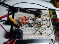
By the way I finalized the L-Adaptor circuitry (a linear series element low noise PSU as an SMPS brick replacement attempt for many uses).
It can be set from 1.8V to 18V by deciding with a jumper how many LED segments will be alight. Boots at 18V a 2.5A peaking soldering iron alright for a test. Delivering to it 40W in average. I believe it will be 100W delivery worthy at least. Matter of sinking for sustained or peak demand and proper transformer choice for an application.
It can be set from 1.8V to 18V by deciding with a jumper how many LED segments will be alight. Boots at 18V a 2.5A peaking soldering iron alright for a test. Delivering to it 40W in average. I believe it will be 100W delivery worthy at least. Matter of sinking for sustained or peak demand and proper transformer choice for an application.
Attachments

I wanted to do the same as you but ended up opting for a LT3042 module because the Pi doesn't draw a steady current all the time.Did anyone successfully boot the RPi3 running with UltraBiB reg?
I followed the posts and:
J3 of less than 7.5mA Idss is used;
red type LEDs;
R1: 0.27Ω 5W resistor;
I tried both 1KΩ and 1.5KΩ for R9;
trimpot tuned to 5.14Vdc;(max 5.25Vdc for pi3)
transformer: 50VA / 2x9Vac secondary(parallel wiring);
power via the GPIO of pi3 (pin 4-DC5V and pin6-GND).
Pi3 red light is on but the green light repeats with some weird pattern and it won't boot.
The reg seems okay for standalone testing.
I got a big heatsink for both FETs and it is quite warm, close to 40C.
I test powered the pi3 with the official adaptor and it booted ok.
Any thought?
What is your Pi version? The latest ones use more current than the earlier ones. I continue to use the Pi 2B for this reason. Also, I reduce the clock speed, turn off the HDMI and even the power LEDs and am able to power it using a 550mA linear PSU or the LT3042.
I managed to get an RPi3+ to boot with a 5V UltraBiB set up with standard FETs but down graded to deliver 1A1 (R1 0R54) only which was sufficient for the measured current draw in my application that never exceeded 0A89. However, the UltraBiB ran soooo hot, I was not happy that it would survive long term. I think there are better solutions to power RPi3s; maybe Salas’s L-Adaptor circuit.
It would take bigger sinks for long term reliability. With CCSed shunt topology the big waste is that you must have it idling for top+ demand at all times. Did something change in subjective terms when powering the RPI3+ from a good linear PSU than its SMPS adaptor?
I have not done any serious comparison between SMPS adapter and good linear PSU for the RPi. I am using the RPi in a DDDac but have another issue with it at the moment which means it is currently disassembled and inoperable waiting for some SMD resistors to arrive. Other folks think that linear power for the RPi sounds better in this application. When it’s up and running again, I’ll compare the two
- Home
- Amplifiers
- Power Supplies
- Salas SSLV1.3 UltraBiB shunt regulator