
Hi Salas,
I am building three regs for a Soekris Dam2941. I first built the VD+5V with R1 of 1.2r. Adjusted and measured across VRR and got 156r. Thought whether that was low but removed VR1 and VRR and substituted a 156r resistor and it works fine with steady 5V output and warm M1 and M2.
Next I built the two VA+ and - 5V regs with R1 of 2.6r. This time I decided not to put VR1 and VRR but directly inserted a 156r in place. No leds light up. OK, so I changed to 1kr and then to 3.7kr still no leds light up in either of those two regs.
I compared the two pos regs side by side with no VRR in either. In the good one I got 12.54V after R1 and at the output relative to G. In the bad one I got 10.91V after R1 but only 1.4V out relative to G. The V across R2, R3 and R4 in both regs measure 0V.
Could you please advice. Also, in the notes you refer to VRR as a bypass resistor. I am thinking there must be some clever reason why there is VR1 and VRR in parallel but I dont understand why.
Thanks. nash
Hi Nash,
VRR is there to parallel the trimmer.
A. For bringing its max value down restraining max Vout to spec at its end stop. B. To ease some dissipation off the trimmer and also help its quality characteristics. C. To still have a current path in case the trimmer's wiper gets damaged or wears out.
So what resistance you measure across VRR when the trimmer is installed its the combination result of VRR//VR1 at whatever travel point VR1 is set at the time.
You may have reversed LEDs or some broken transistor (Q2?) in the VA regs. Or a Mosfet type got mixed up.
In any case install all standard components first, try the regs out again, see if you still need to troubleshoot.
When all is well you can go measure across VRR and substitute with single resistor as you did in the VD+ one.
Ok. I found the problem. I had accidentally switched the two IRF M2s. This on the joint + and - PCBs.
I recall having inserted the two M1s and the two M2s into the boards, having placed them on the aluminum sheet for marking their holes and then moving them off to the side. After attaching the mica insulators to the aluminum I had picked up the PCB and at that time one M1 and both M2s just slid down. To make it easier I turned the PCB over and inserted the missing M1 and inserted the M2s in the same positions they dropped down. Of course they were opposite since I had turned the PCB over!
Thanks for all your help. Appreciated. nash
Nice that you found the cause. Good that no part got damaged from the MOSFETs reverse position error when test powered.
Bonjour, j'ai des doutes sur la qualité des résistances que j'ai achetées pour R1.
résistances bobinées vishay à travers le trou 2 watts 1 ohm 1%
résistances bobinées vishay à travers le trou 2 watts 1 ohm 1%
"Hello, I have doubts about the quality of the resistors I bought for R1. Vishay wirewound resistors through hole 2 watts 1 ohm 1%"can a moderator translate my post, please I thought I did it
Hi, have no doubts, those are fine resistors for this job.
Thank you Salas, you are great, we can always count on you!Hi, have no doubts, those are fine resistors for this job.
Hi, this is not a steady figure, it depends on individual configuration. C2's chosen value and Vout setting make a certain ramp up charge time (works like soft start also). Then the output load consumption average and the shunt's spare current setting in combination with C3's chosen value make a drain rate.
What you can do if you have a DSO (digital storage oscilloscope) is probe the output of your individually configured and loaded Ubib, use single trigger mode, set trigger threshold at 10% Vout, use slow capture time (horizontal) then power the Ubib on. The DSO will hopefully capture the ramp up slide and freeze. Else play with the trigger threshold and horizontal scan, repeat until it does. Use the DSO's cursors menu to home in and measure the Y&X points. 10% to 90% voltage figure vs time figure on screen is your yV/xS. Convert to V/uS.
What you can do if you have a DSO (digital storage oscilloscope) is probe the output of your individually configured and loaded Ubib, use single trigger mode, set trigger threshold at 10% Vout, use slow capture time (horizontal) then power the Ubib on. The DSO will hopefully capture the ramp up slide and freeze. Else play with the trigger threshold and horizontal scan, repeat until it does. Use the DSO's cursors menu to home in and measure the Y&X points. 10% to 90% voltage figure vs time figure on screen is your yV/xS. Convert to V/uS.
Thank you Salas for explanation!
But it is a bit complicated to make a test. I wanted to use UltraBib in output stage, so wanted to determine if it is suitable for this. For example LM3045 brings 25 V/μs slew rate. Could you approximate figure out how much it will be for UltraBib?
But it is a bit complicated to make a test. I wanted to use UltraBib in output stage, so wanted to determine if it is suitable for this. For example LM3045 brings 25 V/μs slew rate. Could you approximate figure out how much it will be for UltraBib?
Hi, don't take a PSU's "slew rate" as something to match with an op-amp's figure. Don't worry about it. PSUs take mS not μs to ramp up. Due to their large capacitors. After they are there charged up to Vout, then its just DC.
Another instance with slew would be what's the recovery slide time when loaded to full current with a transient load cycle. And how it looks for possible ringing. But that's a situation say for industrial supplies. No way an audio op-amp will bring an overbuilt PSU to its knees.
Another instance with slew would be what's the recovery slide time when loaded to full current with a transient load cycle. And how it looks for possible ringing. But that's a situation say for industrial supplies. No way an audio op-amp will bring an overbuilt PSU to its knees.
Hi Salas,
In my previous builds I have always used the fattest and shortest connections from the Ubib boards to the load usually 14 or 16awg.
In connecting to the dam 2941 I find that the dam 2941 board has an MTA 156 connector and the largest wire that can be used is 18awg. Never used these before so what to do. Solder a 16awg to the top of the connector or use the KK series crimp connectors? Also, do you have a preference for solid or stranded wire for board to load connections. Ubib boards have the screw wire terminal blocks.
Thanks. nash
Nash hi,
Better crimp I would say. Stranded is easier laid out. If I want to be fancy I tease out insulated solid core wires from an old leftover length of Kimber 4TC speaker cable. I run them side by side and I shape them with the pliers to follow route. Tie wraps can be added too along the way. Shaped solid core cable routes look structural like in some old carefully handmade amps.
Better crimp I would say. Stranded is easier laid out. If I want to be fancy I tease out insulated solid core wires from an old leftover length of Kimber 4TC speaker cable. I run them side by side and I shape them with the pliers to follow route. Tie wraps can be added too along the way. Shaped solid core cable routes look structural like in some old carefully handmade amps.
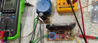
Very good I have finished making the regulator, simply thank you Mr. Salas for this great design and share it with us all, I am very grateful.
The regulator works very well, it is for a preamplifier that I am making and I needed a regulated negative voltage, of only 23ma, I have had it working for about 1 hour and with the multimeter I have not seen oscillations in the voltage as well as the current, the temperature of the heatsink is only 36ºc, with an ambient temperature of 23ºc.
The only question, if I may, is how to detect if there are oscillations in the regulator.
Regards😊
Attachments
Hi, nice diy job, congratulations. To look for high frequency oscillations it takes an oscilloscope AC coupled and set at sensitive mV scale connected to a probe on the DC output with short ground wire around nose. You want a clean horizontal trace, no distinct waveform riding on it. As you sweep the time knob If you catch a sinewave or sawtooth pattern (usually reminding of but distorted) its sure oscillation. Can be near MHz or few MHz with tens or hundreds mV peak to peak. Side effects to make you suspicious if not having a scope can be: DC output instability, inexplicably hot transistors, buzz on the client circuit, if you bring near to the circuit an AM portable radio it catches oscillation interference making noise on its speaker.
- Home
- Amplifiers
- Power Supplies
- Salas SSLV1.3 UltraBiB shunt regulator