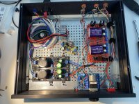
Congratulations for your build & nice that you like the sound. Is there a picture to share?
The Ubib has no problem to handle 18V across it. Though it creates 4.5W dissipation for M1 when you will set 250mA CC.
The Ubib has no problem to handle 18V across it. Though it creates 4.5W dissipation for M1 when you will set 250mA CC.
It is a board from China where I replace apot with the Alps pot.Nice. Is the motorized pot Panasonic?
(Keyboard slip but I refilled the post)
Next step is to move the Muses volume control from the other preamp I have.
One more question pls.
I am considering to put 2-3 regulators into a dedicated chassis.
The cable length between regulators and the preamp & volume control will be around 1 meter + internal cabling around 30 cm. So, in total 1.3m = 4 feet.
Would you advise any extra compensation at the preamp board (some capacitance) for such lengthy wires?
Such lengthy wires are going to add output resistance. Depending on the nature of the loads they might degrade the perceived performance vs having the regs installed in the same box. Steady bias circuits might be less affected. But big current swings modulate voltage drop across cable resistance. Use thickest cables practical.
As for instability compensation I don't think it is going to be needed. I had tried one meter test leads as output wires during the Ubib's development and it remained stable. You could add 10uF tantalum locally at the receiving ends for decoupling from the long incoming wires inductance. In case you will get stability problems in your installation let us know specifically so we will think of possible measures.
As for instability compensation I don't think it is going to be needed. I had tried one meter test leads as output wires during the Ubib's development and it remained stable. You could add 10uF tantalum locally at the receiving ends for decoupling from the long incoming wires inductance. In case you will get stability problems in your installation let us know specifically so we will think of possible measures.
To use a TTL level Mosfet for M2 of low Vgs (th) like the one in Reflektor, to use one LED only by shorting the other, to use 5mA IDSS J3 so to have lowest Vgs (off). That is for 3.3V. For 1.2V only the L-Adapter can possibly reach so low.
May I ask if anyone did this mod and uses the ultrabib at 3.3v ? Which parts did you use in the end ?
...found it and ordered the parts and will try...Not as it is, circa 5V down limit is its stated spec, so yours works as intended. If you want to try the possibility of shorting one LED, replacing M2 with a Logic Level MOSFET like the MTP3055VL along with changing R9 to 2.2k, it may work well enough down to 3.1V limit or not but I did not originally intend it or check it in that way. There will be no negative mirror lower voltage version if made so.
By the way, the Vrr resistor's value which runs across VR1 can set a tighter bracket to the adjustment region if you intend the reg for low voltages only. Say 3.3V to 12V. Small Vrr forces VR1 to smaller too. So you get less bottom to top span but more within range resolution on the trimmer too.
Hello i have a problem with salas 1.3bib, sory i have an problem with four salasys😉 transformer have 10ac. So i have 14.7vdc on first capacitor. But all salasys have 14,7v out. Trimer dont change anythink. Leds dont work. If my pf5102 jfets works i have ids near 6 or 8mA. Where i should find a problem ? Mayby 270resistors are to smal for that ids? Bye.

From previous experiences first turn the 20k VR1 many times until its value goes really down because it has large 5V-40V voltage range. If the problem remains let us know so to think of what to try next.
Hello. Sorry but turning trimmer dont change any think. Full dc on output. Im thinkig that problem is with pf5102, becouse 4 salasys dont work corectly. Mayby change 270ohm resistors near pf?
Did you turn the trimmers in both directions? Clockwise & anticlockwise?
Are they official boards so we can exclude routing mistakes? One thing to keep, its a systematic error. Can't be performing same way wrong in four sections just because of bad luck. So lets look for that mistake or failure.
Maybe its about M1 or Q2. More probable. First a thorough visual inspection. Make sure they are the proper types. Then make sure no other component is populated systematically wrong either for type or orientation. A photo would also help.
Correct Vgs for the IRF Mosfets is 3-4V (voltage between legs 1 & 3). For FQP type 4-5V. Correct Vbe for BC transistors is 0.55-0.65V (legs 2,3). Good voltage over 270 Ohm resistors is 270mV-540mV leg to leg. If you see no voltage drop on such a resistor, means the associated JFET does not conduct. Do check all those voltages.
Hello. Jest i try it on both diredtions. Probybly pf5102 jfets are fake, dont know why when i try to measure 6 pc of this j fet i get wrong drain and source legs, sometime i get
NPN . I will try it once again like you writed to me.
NPN . I will try it once again like you writed to me.
Okey last time. Transistor are corect. Full 14.7v dc output from 10ac transformer .Vbe for 9610 is 14.7dc, from 530 is 0.62v. Q3 have 0.23v, Q2 0v, Q1 0v. Only R8 from 270ohms resistors have voltage, 0.45v dc. Others 270ohms have 0v.
If you bought PF5102 from dubious source and giving weird test replace with J113 from reputable source and apply as in my first post link instructions. Also test your 9610 on the component tester.
- Home
- Amplifiers
- Power Supplies
- Salas SSLV1.3 UltraBiB shunt regulator