Hi Salas,
I see why you did this,It's like paralleling if that makes since low R or cancels the leads ,Great Idea,and I will read Kevin article further,
is a heavy gauge wire better here,I wire power stuff with 16 to 18 anyway.
Does the heatsink at the outputs ever get hot? mine run at almost the ambient temp, the one in the middle about 15 or so degrees hotter,I think these heatsinks are larger than what was called for but I like 'em,lol
I have the boards (2 5's to 35's ) in circuit now and are running fine, I will make the sense wiring change and let them cook for a day or two,
Thanks for your input and help ! 😀
Heavy gauge helps when running normal two wires. When running 4 wires there is no need to be heavy. Don't forget to clip the local board jumpers between sense points and +/GND outputs for remote sensing to work properly when moving from 2 wire to 4 wire mode. What gets hot has to do with how you set the reg's CCS and what is your load's consumption. This is a 'super reg' I.e. runs on constant current, this makes it steady to outside world input side, but it also means that what mA you set on top of your consumption demands, its absorbed in the output loop and heats it up. Set about +100mA your top load demand at CCS so to have enough residual left for 'massaging' the shunt Mosfet bias and dissipating logically.
hi Salas,
I will do that,
Thanks for the info,Gee I am learning alot,kinda green to fet's OLD bipolar boy here,lol.
A question,
I am seeing more and more places where people are separating supplies,like in a dac,Brain's GT clones, one trans for one PS board to a voltage,if you ferrite and add a cap,IS there a difference?
I noticed amps are running dual secs and two reg boards to one amp,I have 8 active channels,8 amps, a DAC and a few other things that need power,Am I going to need 20 transformers and ps boards to run all this or can I feed several from one supply,like we used to do, LOL,🙂
Suggestion are welcome 😛
There must be appreciable interference so to decide more individual supplies in systems. Having very low in mOhm and flat in frequency output impedance from a supply is key so to be able to use less units since different stages fed will find not enough power source impedance to modulate by their dynamically different current demands. The shunt reg with remote sensing goes a long way towards that goal. Keep it simple.
the CCS and Shunt devices dissipate the Vdrop * Id.
The two parts have different Vdrop and different Id.
They can be arranged that the CCS has the higher dissipation in normal operation, or that the Shunt has the higher dissipation in normal use. During these times of normal use I would suggest that Tj<<150degC preferably <80degC.
However there are abnormal conditions during which most users would not want their expensive regulator to destroy itself.
The worst case dissipation for the CCS is highest mains voltage and a dead short across the regulator output.
The worst case dissipation for the Shunt is no load on the output.
The worst case CCS is always higher dissipation than the worst case Shunt dissipation and they these two worst cases can never happen together.
I design the heatsinking of both the CCS and the Shunt for worst case conditions, but since I know these conditions are rare and probably short term I will allow much higher Tj while the fault is active. Tj ~125degC for a 150deg device and Tj~150degC for a 175deg device.
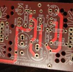
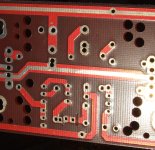
Board modification
Andrew
Is this the section that you mention for the board modification with the zeaners?
Thread this as an example circuit.
Andrew
Is this the section that you mention for the board modification with the zeaners?
An externally hosted image should be here but it was not working when we last tested it.
Thread this as an example circuit.
That looks like an HV regulator.
I have not worked on an HV version.
My limit so far is 99Vdc input and 62Vdc output.
But I intend to move to ~80Vdc output.
The mods I am referring to are in the monitor voltage and output a control voltage.
That HV schematic does not show the circuit in the new versions of the LV that have clearly separated CCS, Shunt, Sense parts.
The sun is out.
I'll get some pics today.
Have a nice photo session Andrew 🙂
+1
I wait also Andrew's photo to see his upgrade🙂
PCB modifications to Vref
Trace cuts next to R6 allow extra LEDs/diodes/Zeners to be added to the Vref string.
The schematic shows the Vref string, both the <5V and >5V versions.
The output voltage trim adjustment is moved to the CCS source lead. 0r0 to 200r gives an adequate trim range.
More to follow.
Trace cuts next to R6 allow extra LEDs/diodes/Zeners to be added to the Vref string.
The schematic shows the Vref string, both the <5V and >5V versions.
The output voltage trim adjustment is moved to the CCS source lead. 0r0 to 200r gives an adequate trim range.
More to follow.
Attachments

Trace cuts next to R6 allow extra LEDs/diodes/Zeners to be added to the Vref string.
The schematic shows the Vref string, both the <5V and >5V versions.
The output voltage trim adjustment is moved to the CCS source lead. 0r0 to 200r gives an adequate trim range.
More to follow.
Thanks, for sharing these modifications!
Changing 2sk170 to Bf244A helps also the Vout stability?
I am trying to use the low voltage schematic for my turntable DC motor (2.71v 300ma maxon 110191- origin live DC100) but over the time I have small speed changes!
Hi,
specifying obsolete 2sk170 where they offer no advantage is a waste of expensive resources.
The bf244a are any readily available, cheap, lower transconductance higher Vgs, Nchannel device. It has no special characteristic to improve temperature compensation.
A DC motor run from a DC supply without speed control feedback has little hope of maintaining constant speed nor consistent speed.
*There are points of interest between using K170BL or BF244A for active error amp load in those CCTs. Like marginal pinch off for Q5 especially in the under 5V BJT output section when comparable in IDSS samples to BL are chosen for same 20kHz Zo performance in all sections.
Trace cuts next to R6 allow extra LEDs/diodes/Zeners to be added to the Vref string.
The schematic shows the Vref string, both the <5V and >5V versions.
The output voltage trim adjustment is moved to the CCS source lead. 0r0 to 200r gives an adequate trim range.
More to follow.
Why there's still a trimmer in Vref section if the trimmer moved to CCS sources lead. Bit confuse here.
I consider any variable resistor to be temporary only.
Use the minimum resistance to set the voltage you need, then replace with a fixed low tempco resistor. Then final trim in the source side of the CCS and again replace with a fixed resistor. I have some nice 1W 100r pots that I can use as temporary VR for setting up.
Use the minimum resistance to set the voltage you need, then replace with a fixed low tempco resistor. Then final trim in the source side of the CCS and again replace with a fixed resistor. I have some nice 1W 100r pots that I can use as temporary VR for setting up.
*There are points of interest between using K170BL or BF244A for active error amp load in those CCTs. Like marginal pinch off for Q5 especially in the under 5V BJT output section when comparable in IDSS samples to BL are chosen for same 20kHz Zo performance in all sections.
Thanks to let us know, I will use SK170BL as usual.😉
- Status
- Not open for further replies.
- Home
- Group Buys
- Salas low shunt Group-design by Salas