Don't know but the outcome points to some oscillation that you solved related to mounting parasitics. No scope data, no pictures, so no firm answer.
Andrew the data I supplied may have been misleading Vg13.1 and Vd 13.1 just happened to be equal. I don't get continuity between them (at least when power is off).
I took another data point with variac a bit higher to give -18.7 at source pin.
Now Vg is -15.3 and Vd is still -13.1.
So Vgd is 2.2
It seems to me that on the CCS FET the gate to drain relationship is wrong?
So it seems to me there are two possible causes:
A) the gate to drain relationship for the CCS FET is wrong or
B ) The shunt FET is not conducting enough current to ground.
Now I notice that Vg for the shunt FET is about 3 volts bigger on the side that is out of range (negative side).
So perhaps I need to troubleshoot the part of the circuit that sets the gate voltage at the shunt FET?
Does tha sound right or am I off course?
The sensor circuit may be the culprit.
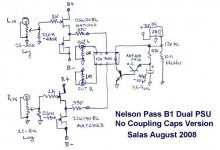
Measure the voltage at every node from ground and mark on the schematic. Post a pic of the marked up schematic.
Measure the voltage at every node from ground and mark on the schematic. Post a pic of the marked up schematic.
Today i've rebuilt the DCB1 on a better pcb (etched by myself) and used only good quality components but on the positive reg something is wrong.
I have the following measured parameters:
IN=15v,
Out=14,25V,
Across 3 leds=5,5v
Across 5 Leds=12,75v
Across R that sets the current (10ohm)= 0,83
Any clue what to check ?
I have the following measured parameters:
IN=15v,
Out=14,25V,
Across 3 leds=5,5v
Across 5 Leds=12,75v
Across R that sets the current (10ohm)= 0,83
Any clue what to check ?
Attachments
Too strong Leds maybe? Needing higher secondary? Do all mosfets show 3.5-4VDC between pins gate, source?
The negative rail is working and measuring good without load.
I've measured Gate-Souce voltage and i have 4.6V on CCS and on the other mosfet i have 0v.
The leds are a bit lower than the other rail. The red leds are 1.8 and the green ones are 2v.
After the other channel is working i will install also some heatsinks. Is strange because i had the DCB working but i wanted to use a better pcb and the delay based on relay.
0V is bad, replace that part. Maybe it died for dissipating all available current without load to share some and no sink to help it out, or it could had been hit with static during storage and handling. Also check continuity of the traces that connect to it.
I've solved the shunt. The problem was a resistor not soldered well.
Now i'm fighting with the relay part. The relay does not click, after few seconds voltage goes to 0.8V across relay. If i make a shortcircuit between Base and Colector of the second transistor the relay clicks. I'm using 2xBC546C and two paraleled resistors 560R as i'm using a 5V relay. I tried to change the electrolitic from 100uf to 47 uf but only change is the time when reaches 0.8V and that's all.
The circuit is so simple ... and is impossible to find the problem.
Attachments
Last edited:
Use single BC517 or bootstrap with 0.1u from base to collector provided the traces are true to the schematic around the delay circuit.
![HYPNOTIZE_IMAGE[1].jpg](/community/data/attachments/262/262920-4a33cfbe398870e222166a9b5e3eb717.jpg?hash=SjPPvjmIcO)
With the original P2P proto's telecom relay wasn't needed, with the standardized types later its needed to use BC517 but if not handy, the cap fixes it.
Installed that cap but there is no change. I have the same 0.8v on the relay coil.
I will search tommorow for a BC517.
I will search tommorow for a BC517.
Look for other things also, do you have the diode correct there for instance? Is the relay the proper pins and type? Look thoroughly. If it was just the transistor it would work with the cap fix.
It was the same behaviour also without diode. When i short the B-C (where is the capacitor now) the relay clicks and i have 4.8V on the relay coil.
So the relay is well positioned and the diode is not making anything bad.
So the relay is well positioned and the diode is not making anything bad.
- Home
- Source & Line
- Analog Line Level
- Salas hotrodded blue DCB1 build