Hi Salas, what the value of the impedance with 600mA output current and 2A?
340uOhm & 220uOhm. Diminishing returns in other words after 1A.
340uOhm & 220uOhm. Diminishing returns in other words after 1A.
Thanks Salas! 😉
My Tea-bag kit is up and running since a good few days, and I have to say it is sounding very good. There is a lot more 3d and stable imaging going on compared to the normal b1. The difference is so big, its more then a full step up.
Thanks allot Mr Pass, Salas and Tea-bag, my stereo sounds fantatisc now.
Thanks allot Mr Pass, Salas and Tea-bag, my stereo sounds fantatisc now.
Congrats! But you know what we say here? With no pix it did not happen.😀
Just joking. If you got some pictures of it in your system members are always happy to look at.
Just joking. If you got some pictures of it in your system members are always happy to look at.
Congrats! But you know what we say here? With no pix it did not happen.😀
Just joking. If you got some pictures of it in your system members are always happy to look at.
+1 😉
Regards
My Tea-bag kit is up and running since a good few days, and I have to say it is sounding very good. There is a lot more 3d and stable imaging going on compared to the normal b1. The difference is so big, its more then a full step up.
Thanks allot Mr Pass, Salas and Tea-bag, my stereo sounds fantatisc now.
High-end audio without the price. Brings a tear to my eye 😀
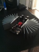
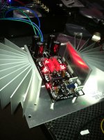
Here's my build so far. I went with Caddocks and TX2575s on the IN/OUT branch.
I just need to match the LEDs for Vref and CCS. I'll do that today and get some woodworking done tomorrow.
Attachments
Hi,
I just finished the kit from T-B. All LEDs up. The Vdrop on R1 was about 2.0V at V+ side, but it was only 1.7V at V- side. And they would drop to about 1.95 and 1.66 after a few minutes. One side Vdrop seems to be border line (2 +/- 0.3V).
Also, the V+ measured to be about 10.05 and V- to be -10.14 so that V- was actually slightly higher than V+. Output DC offset was about 2mV and 3mV at L&R channel. The fact that |V-| > |V+| worries me. I am not sure if there is something that need to be fixed?
When I matched the LEDs, I only use the diode mode on a Fluke 179 and read the voltage. Was that not the "good enough" way to match LEDs?
Thanks a lot for your help!
Last edited:
The Fluke 179 luckily has a 2.5V diode test spec and gives results for LEDS also, but any meter to save its battery never gives more than essential current to turn them on. Hence it won't give a reference measurement at the current range they see in our specific circuit. BUT your PSU results are no problem for the DCB1 tolerances. Your DC offset is not spectacular but in spec too. For mostly aesthetic reasons you can try to near the running currents in both CCS. The -V side drop is weaker due to different Vgs of your POS and NEG Mosfets. Use ~25% less setting resistor value on the negative CCS. I.e. 10R on POS and 8.2R on NEG as it is set now, or 5.6R and 4.7R for a hotter running system @ ~350mA if you feel your sinks cool enough now. It usually becomes even nicer when running higher. Do those things in leisure, your DCB1 is good for use as it is.
Thanks a lot for your help!
So if I want to be mister perfect, the 5 LEDs group (most relevant?) need to be desoldered and re-matched?
Since I will use it for headphone, how can I reduce the DC offset at output?
So if I want to be mister perfect, the 5 LEDs group (most relevant?) need to be desoldered and re-matched?
Since I will use it for headphone, how can I reduce the DC offset at output?
Don't change the LEDs.
The output offset is determined by the accuracy of selecting jFETs with the same Idss.
The output offset is determined by the accuracy of selecting jFETs with the same Idss.
Thanks for the reply!
I did more reading and realized that (self-monologue):
1. The difference of Vdrop across R1s (10R 5W) probably caused by resistance difference. But perfect matching of them (now I have 1.95V and 1.66V) is not absolute necessary.
2. The DC offsets were caused by JFET and the means to reduce them is to get better matching. Mine power amp is Aleph3 which has 20dB gain. So I may want to rematch those JFET later.
3. My LED matching may not be perfect (due to the limitation of diode mode of DMM), but they have much less effect comparing to the two effects above.
What I couldn't figure out is why the building note suggest +Vout will be slightly higher than -Vout.
Thanks for some correction to my monologue and explanation.
I'll give it a listen tonight and will upload some photo if things go well ...
Last edited:
1. The difference of Vdrop across R1s (10R 5W) probably caused by resistance difference.
Oops, just re-read Salas comments and pay more attention now. 😱
The -V side drop is weaker due to different Vgs of your POS and NEG Mosfets. Use ~25% less setting resistor value on the negative CCS.
What I couldn't figure out is why the building note suggest +Vout will be slightly higher than -Vout.
...
That note comes from the original version Mezmerize where I deliberately mismatched the polarities a bit for creating more second harmonic and aiding offset in a low CCS, not heatsinked, small size aim. The hot rod Hypnotize naturally presents a bolder tonality due to PSU boost and the symmetry I restored in the local Vref CCSes by orthodox design.
Oops, just re-read Salas comments and pay more attention now. 😱
Resistor differences can add to it also, but with modern parts tolerance spec they aren't the main contributor which is VGS given that reasonably close LEDS are used.
Confused...
Tonight I hooked up 4 RCAs and 10-k step attenuator from ebay.
Output: RCA_L/R to output connector_L/R, both RCA_ground were connected to the center pin of the connector on board. RCAs were not mounted (isolated).
The RCA connector has two plastic rings sandwiching the metal ring (lug) where I soldered avwire and connected to the center pin (signal ground). This is my 1st time using these RCA with isolator. When I tighten the nuts, the metal lug I soldered was disconnected from the barrel of RCA, which is confusing to me as a noob. So I "thought" all RCA ground were connected during the test, but they actually may not, depending on if the nuts were tightened.
I test DCB1 with cheap active speaker. I head music with some background buzz. It does not get louder with the pot on B1.
I measured the DC offset at DCB1. They were about 2mV as usual.
I might disconnect and connect the input/output RCAs when DCB1 was on, which I probably shouldn't. But I was spoiled by Aleph 3. 😱
Anyhow, when I turn everything off and found out the RCA ground problem (mentioned above). I also found now the signal output L/R and ground are now shorted. 😱
And I measure across the 1M ohm resistor (still soldered on board) around output connector and they are both shorted. I wonder if I kill something?
Thanks for the help!
Last edited:
The relay shorts output to ground in mute or off phase. Just power it on without any amp connected and see if you got your known DC offset. That would be indication all is well and try listen to music again on the cheap active speakers before you attempt connecting any valuable amp and speakers.
Thanks! That was one of my optimistic guess.
I powered it up and read the same DC offset. I guess all is well. 🙂
I'll study more on how to connect those RCAs. I hope is that once all the grounds of RCA and signal are connected. That buzz will go away! I'll try it tonight.
I powered it up and read the same DC offset. I guess all is well. 🙂
I'll study more on how to connect those RCAs. I hope is that once all the grounds of RCA and signal are connected. That buzz will go away! I'll try it tonight.
RCA
After checking on the RCA connectors, I realized that the two plastic rings, metal lug and nuts need to be re-sorted in order to work. After sorting out 4 RCAs and connecting to active speaker, there is no more hum anymore. Great!
Unfortunately, when I was about connect it to Aleph 3, I found out something that I never knew. So I did not try DCB1 on A3 yet. I will sort it out first before trying.
- Home
- Source & Line
- Analog Line Level
- Salas hotrodded blue DCB1 build