Its there many many times in the course of the threads. Any late comer could open a DCB1 short guide FAQ thread though.
*Correction, you can use the left off parts as multi input switches only, the way I showed the cut, fed from +V/GND 5 or 12V PSU given the relays at hand.
Ok, so I missed it... But I did look and try to figure out what was what with the various threads and DCB1 designs. Thinking back, I don't think I even found any "DCB1 short guide FAQ", so that would explain it.
All the relevant threads you see I am not the starter. But I try to answer any question I spot. In your case you could ask Tea when getting the boards or post in one thread, I am sure very many would guide you if not me seeing it first. Anyway, looking forward to see your work in progress.
I can see it in the BOM. I hope DimZ did not put 1K there. It is to check currents when setting for reg use only following the guide steps thread. You may jumper if for fixed DCB1 use.
no, I used 1R
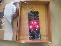
the orientation of the leds is right (the triplets are on but not the quintets), I'll try to check them on board or change them all to see if there is a chain break...
Last edited:
Use 9V battery and light them one by one with 2 wires before attempting taking them all out. Do it fast or use 1k in series.
I'll do that with the 1k res ...
Success! Have a cigar.")
I will certainly have !!! my humidor is full
thanks
besides dc offset, and voltage across R10, what else of critical importance is there to measure ??
Nothing more. Measure pleasure spinning a couple of fav recordings. Will come up smoother in 48h for the Ecaps to shape up.


A short update after a little experiment I made this weekend. Bulk / random input and output wires were changed to 1mm solidcore Cu. It came from genuine CT 100 coaxial cable. It's a pity, I can't provide pictures... On the output I've left semi-air spaced dialectric from the same cable. On the input I left them naked. Too rigid to bend.
A I had a huge smile after plugging the buffer to my system. The singers came back to my room! All in all, now it sounds terrific!
Takman carbon resistors and a DACT style pot are on the way. I wonder if I need changes now
As well, I'm interested, weather I should find some insulation for the naked copper? Or maybe my old wires were so crappy, that any other solid copper wires (insulated) will be fine?
Again, hats off to inventers and developpers of this buffer.
Siberia,
Solid core is definitely better. You would get even better sound using .5mm/24AWG or thinner wires for the audio path. Thicker is OK for power.
Air (bare wires) is the best dielectric but not always practical/safe. Also, bare wires can corrode over time, which is bad for copper, but OK for silver. Enameled magnet wire provides insulation with minimal dielectric, but it could be nicked and it's difficult to spot a bare area, it's time consuming to strip the insulation, and you need to keep adjacent wires apart to avoid cross contamination. Cotton is closest to air but doesn't completely seal the wire so some corrosion is possible (waxed cotton is available and I presume that seals it). Also cotton provides a measure of damping. Next up is foamed teflon, then solid teflon. VHaudio has a proprietary foamed insulation that is similar to teflon, but claimed to be slightly better.
Wires made using long/single crystal (LC) technology are also a worthwhile upgrade. The process is called Ohno Continuous Cast (OCC or PC-OCC for Perfect Crystal). OCC is very pure (six or seven nines), but goes beyond that to eliminate the crystal boundaries in the metal which are said to damage the signal. OCC copper is said to sound better that 4N silver. OCC silver is available, but hard to find and very expensive though.
Silver is said to be better than copper, but is system dependent (too harsh and bright in many systems). Given how expensive it is compared to OCC copper, it may be too hard to justify for many people.
Thin, pure, solid core, OCC wire with a dielectric closest to air makes a difference. The thin wire makes for fragile interconnects, but is just fine for hook-up wire.
Micheal,
Thank you for the nice sum up on signal wires. It's really helpful.
Next time I might look up for OCC copper.
Last week, while adding takmans to my cart, I've grabbed 22 AWG TPFE insulated, silver plated solid copper. I will report, if I switch my bare 1mm Cu to it.
Thank you for the nice sum up on signal wires. It's really helpful.
Next time I might look up for OCC copper.
Last week, while adding takmans to my cart, I've grabbed 22 AWG TPFE insulated, silver plated solid copper. I will report, if I switch my bare 1mm Cu to it.
Its nice you like it. Happy auditions.
Mr Pass and you deserve tons of respect ....... !!!
Whatever brings no hum in a given system. As GND is routed on the DCB1 pcb you can just plug the in/out returns to the pins they go and check it floating from buffer's chassis first with your amp. That was sufficient to most presentations here. A breakdown safety floating scheme like yin yang heavy diodes can be added from a main GND point to chassis. You can run a cable from middle trafo gnd screw terminal for example straight to buffer's chassis if you will notice some hum when floating, before planning a star.
- Home
- Source & Line
- Analog Line Level
- Salas hotrodded blue DCB1 build