Frank you are welcome, congratulations for your builds.Going to build another one so I'll have two, one for headphones only and one for the stereo system.
Thanks Salas and Tea for making this availble for us non-engineering types.
Cheers
Frank M
Thanks for the update, nice when there is positive progress.
Hi,
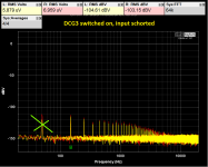
I have been investigating the issue of harmonic noise in my DCG3.
I have posted below again a picture of the spectrum measured at the output with the preamplifier on and the inputs shorted.
I was able to find the source of the peak at 50Hz, these are the 230VAC coil relay that I use to turn on the amplifier. After bypassing these relays, the 50Hz harmonic disappears completely (unfortunately, I did not take a screenshot ) however, all other harmonics (150Hz, 250Hz, 350 Hz ...) remain unchanged.
I tried changing the position of the transformers, inserting shields (copper and steel) between the transformers and the electronics boards, the harmonics remain the same - without the slightest change.
Does anyone have an idea what could be their cause? maybe the rectifier bridges? - In the bridges the diodes are bypassed with parallel 100nF capacitors.
Attachments

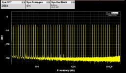
I've been thinking about that, too. But I'm not sure that the way it behaves supports such a thesis.Can the rest be a feature of the measurement loop?
With everything plugged in and the preamp off, there is complete 'silence' on the graph. Harmonics appear immediately when the DCG3 is turned on, even before the output relay is triggered, and remain unchanged after it is triggered.
Does this behavior match?
How to possibly check whether these harmonics are related to the measurement circuit or to the preamplifier itself?
Could be magnetic field interference on the internal signal cables and/or the chassis/terminals. Since the little spikes appear before the signal output relay acts. Try connect/disconnect the chassis with the signal ground? Let's not forget its not easy to nail it because we deal with mainly -120dB below reference spikes here i.e. very very low level harmonic noise to start with.
The other completely harmonic noise free measured examples shown here use either DCSTB or UBiB 1.3 supplies and have the transformers flat on the bottom panel are their main differences to your build. If it has anything to do with what regs. But I would first be suspicious of the transformers different placement and the much mains AC wiring near the signal connectors.
The other completely harmonic noise free measured examples shown here use either DCSTB or UBiB 1.3 supplies and have the transformers flat on the bottom panel are their main differences to your build. If it has anything to do with what regs. But I would first be suspicious of the transformers different placement and the much mains AC wiring near the signal connectors.
Thank you for your input.
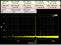
I tried connecting and disconnecting the ground to the chassis without any apparent change in harmonic levels. However, I have now tried using other signal cables and got spikes lower by 5 to 8 dB, perhaps, as you write the interference is induced in the cables partly or entirely.
I tried connecting and disconnecting the ground to the chassis without any apparent change in harmonic levels. However, I have now tried using other signal cables and got spikes lower by 5 to 8 dB, perhaps, as you write the interference is induced in the cables partly or entirely.
That's a significant reduction. Congrats. Maybe redressing the normal coax can further refrain it from picking interference. Star-Quad microphone cable is the best against magnetic interference, though in a balanced XLR situation. In SE it loses the essential common mode rejection element. You can nonetheless also try Star-Quad somewhat creatively for SE. One way shielded etc.
Good day, Salas.
I have a question on the subject of wires and ground. I am in the process of building a second DCG preamp. I will be using coax wire as per your recommendation. In the previous posting, your instruction is to connect the G on both ends. I assume this means from the input RCA to the input selector switch. So that would mean a 4 pole switch for the hot/G on L/R channel. Correct?
Also, is this wire appropriate for the job?
https://www.avshop.ca/wire-amp-cable/bulk-wire/canare-gs-4-instrument-cable-by-the-foot
Regards,
Tom
-No pressing need to switch grounds too. But you can.
-That's rather thick cable to handle within chassis I think.
-That's rather thick cable to handle within chassis I think.
What about Lavalier type like the Sommer Cable Cicada SO-D14 or alike? Can combine L&R and its thin/flexible.
''No pressing need to switch grounds too.'' I don't understand and need some clarification, so so sorry🙂.
Sommer Cable Cicada SO-D14. Looking at the picture, Its a 2 conductor plus 1 drain wire. Do you mean L/R sharing the same drain wire for ground?
Sommer Cable Cicada SO-D14. Looking at the picture, Its a 2 conductor plus 1 drain wire. Do you mean L/R sharing the same drain wire for ground?
I-Select board connects as L-Ground-R for instance. Has three pin terminals for each stereo input and a three pin final stereo output terminal. The relays switch the hot signal lines only. In any case you could connect each input RCA pair grounds together then to a common point through such a cable's shield & drain wire, maybe to a short copper bar. You could connect the potentiometer's ground return pins there too.
Thank you for the suggestion.You can nonetheless also try Star-Quad somewhat creatively for SE. One way shielded etc.
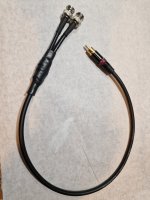
My analyzer has a balanced input (two bnc sockets per channel). Normally when measuring SE I short circuit the '-' socket with a terminating plug.
On your advice, however, I decided to be creative and made a cable using STAR-QUAD (Canare L-4E6S ) cable in such a way that the '-' input is shorted to ground at the RCA plug i.e. close to the source of the circuit being measured.
In this way, I hoped to take advantage of the common mode rejection property also for SE measurement.
It seems to have worked. I attach photos of the cable and the measurements .
Attachments
Salas, good evening.
I am trying to finish dcg3. It is time to troubleshoot what I have fried. Its been a year 🙂
The left psu board measurement: V+ to V- was all over the place but eventually stopped at 19.5V. V+ to ground is 17.95 and V- to ground is 17.88. as you ve said I fried something and should check the transistors. Now I should check all transistors in diode mode (I assume it can be done on the board without desoldering them?). I can desolder and use a transistor checker gadget if needed.
In case I fried Q's can I order replacement parts from my local supplier or must they come matched from Tea Bag? My local shop has 15031/15030 and BC560 550 in stock.
Thanks.
Hi,
Starting with junctions check as populated is a good step.
Transistors matching in the DCSTB PSU isn't critical and you can use spares purchased locally if trusted genuine.
Starting with junctions check as populated is a good step.
Transistors matching in the DCSTB PSU isn't critical and you can use spares purchased locally if trusted genuine.
You also used the component tester I suppose. Initial junctions testing with DMM in diode mode when Q2 & Q4 were still on-board was indicative? Or ambiguous because of the compound nature of the Sziklai pair transistors circuit used in DCSTB?
To be honest it was easier to remove components than test them in situ. This way I can be more confident they work as they should.
- Home
- Source & Line
- Analog Line Level
- Salas DCG3 preamp (line & headphone)