Hello all successful builders of DCG3!
I've ordered the boards and am slowly starting to gather information on this great preamp/headphone amp.
I'd love to hear infos from the already successful DCG3 builders.
Thank You 🙂
I've ordered the boards and am slowly starting to gather information on this great preamp/headphone amp.
I'd love to hear infos from the already successful DCG3 builders.
- What number of DN2540N5-G transistors do I need to buy to select two of the same within 5%? (Mouser)
- If you can, recommend a verified seller for uPA68H on eBay?
Thank You 🙂

1. Maybe 10pcs (better chances if from a same production batch).
2. Hit or miss. Look at the uPA pictures in post #31 see if at least they visually match for shape, print, and logo details.
Good luck with your building efforts.
2. Hit or miss. Look at the uPA pictures in post #31 see if at least they visually match for shape, print, and logo details.
Good luck with your building efforts.
Hi.
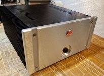
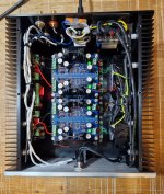
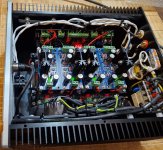
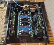
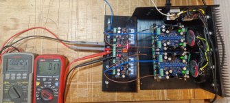
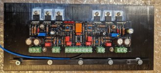
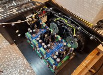
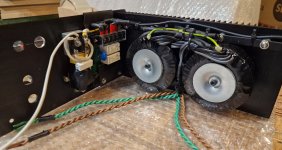
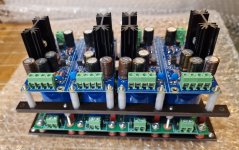
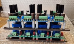
Below are pictures of my build.
I used parts from the Tea Bag kit except for the Jfets. I used a matched 2sk170 quad that I bought more than 20 years ago. The bias is set at 150mA.
In the power supply I used two 50VA transformers followed by four bridges along with CRC filters and two sets of Super Regulator.
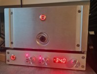
The whole thing was difficult to fit into the enclosure, which turned out to be smaller than I expected. It's tight, but somehow it worked out.
So far I have confirmed that the circuit works. I will report on my listening impressions later.
Marek.
Below are pictures of my build.
I used parts from the Tea Bag kit except for the Jfets. I used a matched 2sk170 quad that I bought more than 20 years ago. The bias is set at 150mA.
In the power supply I used two 50VA transformers followed by four bridges along with CRC filters and two sets of Super Regulator.
The whole thing was difficult to fit into the enclosure, which turned out to be smaller than I expected. It's tight, but somehow it worked out.
So far I have confirmed that the circuit works. I will report on my listening impressions later.
Marek.
Attachments
-
 20240305_172502.jpg766.6 KB · Views: 176
 -
 20240318_191153.jpg453.4 KB · Views: 187
 -
 20240318_190433.jpg683.4 KB · Views: 181
 -
 20240318_190429.jpg706.3 KB · Views: 175
 -
 20240318_130905.jpg616.2 KB · Views: 169
 -
 20240318_110146.jpg407.1 KB · Views: 166
 -
 20240317_190423.jpg410.3 KB · Views: 168
 -
 20240315_101716.jpg522.7 KB · Views: 170
 -
 20240313_183939.jpg379.1 KB · Views: 172
 -
 20240307_165651.jpg406.4 KB · Views: 161
 -
 20240307_165647.jpg376.9 KB · Views: 182
Intricate build in a tight space. Congratulations. Headphones use mainly? Volume setting is external?
Salas,
the output RCAs are below the input RCAs, in place of the speaker terminals of the enclosure that was originally intended for a speaker amplifier. These outputs will be used, although I mainly listen on headphones, as you have guessed.
The volume control is a resistor ladder in a separate enclosure. The ladder has a fixed 2kOhm output impedance. On your advice, I added 3kOhm at the DCG3 input to mimic a 10kOhm potentiometer.
yes, my mistakeNot 10kΩ but 20kΩ pot mimicking is 5k (2k ladder+3k).
Worst case Zout (happens at half attenuation point) of classic series pots is 1/4 their nominal value
Iam waiting for delivery of full kit . Just have a question again. If my Tube DAC has 5v RMS output . Would that cause any trouble for preamplifier ?
Thank you .
Thank you .
It will naturally shorten the volume pot's rotation angle of control to comfortable SPL level vs a 2V RMS standard DAC. Depending on how sensitive the power amp and the loudspeakers are as well. Unity gain is usually beyond twelve o'clock in these builds though. Possibly between two and three o'clock.
Full out it will clip at 12V RMS (i.e. at 34Vpp or bit earlier for the +/-17V power rails used). Because 5V RMS times gain three is fifteen Volt RMS simply don't push it there. No sane power amp would ever accommodate such an input swing anyway. It would clip way earlier. Unless we talk some special gainless DIY power stage.
Full out it will clip at 12V RMS (i.e. at 34Vpp or bit earlier for the +/-17V power rails used). Because 5V RMS times gain three is fifteen Volt RMS simply don't push it there. No sane power amp would ever accommodate such an input swing anyway. It would clip way earlier. Unless we talk some special gainless DIY power stage.
Have you tried your newly built DCG3 for listening to music yet?yes, my mistake
Yes I have.
First I took some measurements that are more or less in line with what can be found in this thread.
I have, unfortunately, a rather high peak at 50Hz (-100dBV while the noise floor sits around -150dBV). Well, this was to be expected from how tight the enclosure is....
However My impression is that it is not audible.
The sound is really good. The DCG3 pairs great with the HIFIMAN Ananada.
The sound is detailed but not intrusive, warm and engaging. It's hard to stop listening. I like it a lot.
Very nice results. Congratulations.
-100dBV 50Hz spike is possibly some low level ground loop due to return wiring. Even because of the magnetic field from transformers and mains in a cramped space. Else it comes from outside. Did your measurements include the external ladder attenuator?
What is a power amp and loudspeakers system to try it as a line preamp next?
Good point. I will repeat the mesurements with attenuator and report later.Did your measurements include the external ladder attenuator?
The power amp is f4 and the speakers at this point are small DIY monitors - Troels Gravesen Seas CURV ( http://www.troelsgravesen.dk/SEAS-CURV_Marek.htm ). I haven't try that yet however....
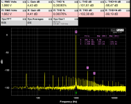
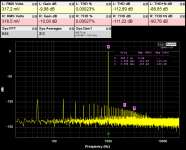
I took some measurements of my DCG3. This time with an attenuator.
For the measurements I set the attenuator to -0dB (even in this setting it has 2kOhm output impedance).
The DCG3 is loaded with a resistance of 22KOhm.
In the pictures are the following measurements:
do these measurements look ok?
For the measurements I set the attenuator to -0dB (even in this setting it has 2kOhm output impedance).
The DCG3 is loaded with a resistance of 22KOhm.
In the pictures are the following measurements:
- FFT for 1Vrms 1KHz input signal - (THD, THD+N and Gain can be seen....)
- THD vs frequency for different input levels: from -10dBV (316mVrms) to 0dBV (1Vrms).
- 2nd and 3rd harmonic levels for a 1KHz input signal and levels varying from -15dBV (177mVrms) to 0 dBV (1Vrms)
do these measurements look ok?
Attachments
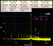
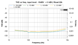
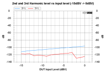
THD looks normal for the test levels used. THD+N looks around 16 effective number of bits. Can reach 18 bits ENOB when testing somewhere between 0.5V to 1V RMS DUT output. Not any or very little harmonic noise helps such figures as well. Is it the same low level harmonic noise picture when without the external ladder attenuator and its connecting cables?
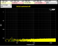
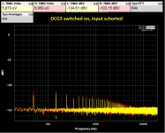
I took measurements with the DCG3 inputs shorted. I am posting measurements for DCG3 switched off and on.Is it the same low level harmonic noise picture when without the external ladder attenuator and its connecting cables?
When switched on, harmonic noise appears, with a fundamental harmonic of 50Hz and subsequent odd harmonics.
Interestingly, the plots look the same before the output relay is switched on (the output is then shorted to ground) and after it is switched on - there is virtually no difference....
How to explain such behavior? I think it is magnetic coupling from transformers that causes this noise....
In addition, I took two measurements with the attenuator. I got the best THD+N (-99dB) for an output voltage of 1.6Vrms and the best THD (-112dB) for an output voltage of 300mVrms. I changed the input level with an attenuator, hence the measured gain values
Attachments
Another data point. I installed the Ultrabib ps (dual mono) in the dcg3 in place of the dcstb. After a few assembly mistakes i got it working. It is very nice and it pains me greatly to say this as i am a tube person but nicer in terms of sound quality (for me) than the Salas 6V6 preamp. The "tube sound" of the 6V6 pre is not present in the dcg3 but I am able to hear "more of the music" or details if you will. So the Salas 6V6 will be taken apart and used for another amplifier project. The difference between dcstb and Ultrabib isn't huge but rather subtle in favor of the ultrabib. I still have to figure out why I get hum when the volume pot is off , the hum goes silent when the volume pot is increased to normal listening levels. Most likely a wiring mistake somewhere. The sound is very nice even with this minor hiccup. Going to build another one so I'll have two, one for headphones only and one for the stereo system.
Thanks Salas and Tea for making this availble for us non-engineering types.
Cheers
Frank M
Thanks Salas and Tea for making this availble for us non-engineering types.
Cheers
Frank M
Your THD results look fine. Regarding the transformers field interference hypothesis, rotate them while running FFT to validate. To see if the harmonic noise residual spikes change. That will be a sign they are involved in the situation. Single turn copper tape around the toroid's periphery had dramatically helped the hum & buzz situation in a shoe box chassis diy power amp once for me. Of course your noise levels are way too low to be directly audible but why not try wipe them out if possible.How to explain such behavior? I think it is magnetic coupling from transformers that causes this noise....
- Home
- Source & Line
- Analog Line Level
- Salas DCG3 preamp (line & headphone)