You should had better used a 1.5K series resistor at one wire end of the 9V battery to can current limit at 5mA and measure each Led's VF individually.It's an old 20y old mastech. It has a combined continuity/led test mode. But tired enough instead of using it I tested with an external battery to ensure the proper operation of the led bar. Connected the battery across 5 leds with the ledbar soldered on the board and used the multimeter to measure voltage drop across 1,2,3,4 leds etc. And then move up to cover all the leds in the bar. I see that the light of the led closer to the heatsink in the third bar, counting from left to right, does not light up well compared to the rest, although the measurements in the DCSTB output seem fine. I dont' remember testing it, but I am not sure. I guess this one will have to be replaced too.
Wise words! And a pretty obvious thing to do. I really don't know what I was (not) thinking!You should had better used a 1.5K series resistor at one wire end of the 9V battery to can current limit at 5mA and measure each Led's VF individually.
Going on with the build, I have ordered a kit for remote volume control. It can be used with 6.3 to 15V AC or DC, and draws maximum 200mA. Can I feed it directly from the DCSTB, e.g. with a voltage divider or a series resistance and a couple of leds? I was thinking feeding the I-select from one DCSTB board and the volume control board from the other.
If not possible, and using a separate transformer, should the DCSTB and the remote control board share common 0V?
Finally for testing the DCG3 on the bench, before final assembly in an enclosure, what heatsink should I use?
It's this one: https://www.hificollective.co.uk/potentiometers/glasshouse-remote-control-kit-motorised-alps.html
Possible. Feed it from the raw DC found on main reservoir capacitors pins of the DCSTBs. But use some form of low output impedance voltage drop in-between raw and the remote PCB to below 15V. A resistor and a 12V Zener or easier a 7812 fixed chip reg, something.
For heatsink it doesn't need crazy C/W capability, roughly a 5 cm by 15 cm or somewhat bigger well finned piece should get you by in testing.
Thanks for the prompt response. One more question,still soldering parts. I have soldered all resistors and rj/z., dip switch and the relay on DCG3 board. I see continuity in hp outs between HP and G terminals on both channels.Did I mess something?
FWIW:
I too use a i-select, with a volume-control-relay and motorized pot.
I took a simpler route and daisy-chained the connections:
i-select from DCSTB (as per Salas' direction), VC powered from i-select and volume-pot / IR-receiver from VC-relayboard...
Probably not the prefect way to go, but works issueless...
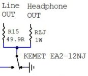
-The relay contact rests at ground position when idle. So the outputs are muted when the relay is not energized. Low impedance repels noise interference from riding the signal lines to connected amplifiers when the preamp is off. Just the small value R15 & RZJ resistors stay in-between. Not high enough to not trigger continuity beeps. You didn't mess something.Thanks for the prompt response. One more question,still soldering parts. I have soldered all resistors and rj/z., dip switch and the relay on DCG3 board. I see continuity in hp outs between HP and G terminals on both channels.Did I mess something?
-What DIP switch?
Attachments
I didn't notice he also has I-Select. In that case he can of course feed raw DC to it and utilize its onboard 7812 DCout connector for a receiver as you did.FWIW:
I too use a i-select, with a volume-control-relay and motorized pot.
I took a simpler route and daisy-chained the connections:
i-select from DCSTB (as per Salas' direction), VC powered from i-select and volume-pot / IR-receiver from VC-relayboard...
Probably not the prefect way to go, but works issueless...

Nice detailed explanation. I was looking at the BOM - guide pdf where in the schematic at rest the relay seems like not connected. Now it makes perfectly sense.-The relay contact rests at ground position when idle. So the outputs are muted when the relay is not energized. Low impedance repels noise interference from riding the signal lines to connected amplifiers when the preamp is off. Just the small value R15 & RZJ resistors stay in-between. Not high enough to not trigger continuity beeps. You didn't mess something.
-What DIP switch?
No DIP switch. It was meant to be the DIP socket for the opamp. Nice confusing typo by me 🙂
@myleftear Thanks for the tip for utilizing the I-SELECT's vreg out.
To sum this up, I can feed the I-Select directly from the DCSTB output terminals and then feed the VC board from the VREG out of I-Select. Seems nice and clean.
No, better feed the I-Select raw DC from reservoir capacitor pins under DCSTB. Not to directly associate the peripherals with the stabilized & filtered power lines to DCG3. More isolation in this way.
In post#1 there are two schematics. The first one which is also in the guide, and in a some details revised PCB release the V1.03. That last long time standard one has the the output grounded when off but the original had it hanging at no connection instead.
In post#1 there are two schematics. The first one which is also in the guide, and in a some details revised PCB release the V1.03. That last long time standard one has the the output grounded when off but the original had it hanging at no connection instead.
Confused a bit, so that would be solder two wires on C1 legs under DCSTB and feed I-Select, right?
Yes
(I had to hold my breath when I did it and switched that thing on🙂 )
(I had to hold my breath when I did it and switched that thing on🙂 )
Indeed that's why I put the LM7812 regulated 12V DC output connector on I-Select's board. To be useful for powering further possible peripherals. That power section with small sink is obviously stronger designed than to just support its own input relays small power needs. 😉I just wanted to mention another viable possibility …

...I would have put a TO-92 12V regulator if it was just for powering a miniature input relay...
Huge thanks to Salas for his design and support as well as to TeaBag for putting the kits together. I have been using the DCG3 powered dual mono by the DCSTB, as a headphone amp, for a couple of months now. It has beaten all other head amps in my possession. Despite being built on a piece of plywood with none of the wiring trimmed to final length, at least until I am finished experimenting and put it in a proper enclosure, it is dead quiet. I originally used a DACT 10k CT2 volume control that I had from a previous project, and it sounded great, but when I switched it out to a 20k Muses based VCX from Academy Audio the sound lost that last little bit of edginess, with no loss of detail. Not an apple to apples comparison I know (10k vs 20k) but the Muses stays. I want to try an autoformer volume controller I have next. My headphones are Audeze LCD-3 and coming from MassDrop HD6xx phones I found them a bit dark with the DCG3. I had a matched quad of Toshiba 2SK170 from a long ago planned DCB1 that I never built, so I pulled the uPA68s and installed the 2SK170s in the header and voila, a perfect match for the LCD-3s, at least to my old ears. No change in detail or dynamics, just like someone washed away the darkness. Maybe a bit less second harmonic? Again a heartfelt thanks to Salas; of the six headphone amps I have or have recently have had, this is the only one I want to listen to.
I know this bit is off-topic but I have to put in a plug for Salas' L-adapter. I recently built two L-adapters, one for my Roon ROCK i5 NUC and one for an Asus network switch and the sound improvement when streaming was jaw dropping. I never realized how much of that grain I experienced when listening to computer music came from the switch mode power supplies. Thank-you for the L-adapter as well Salas.
I know this bit is off-topic but I have to put in a plug for Salas' L-adapter. I recently built two L-adapters, one for my Roon ROCK i5 NUC and one for an Asus network switch and the sound improvement when streaming was jaw dropping. I never realized how much of that grain I experienced when listening to computer music came from the switch mode power supplies. Thank-you for the L-adapter as well Salas.
Attachments
You are welcome. Enjoy.
*Yes the 2SK170s with their higher transconductance bring more NFB into the equation to more contrast. If that's what suits the rest of the system all the better.
*Yes the 2SK170s with their higher transconductance bring more NFB into the equation to more contrast. If that's what suits the rest of the system all the better.
Diy head amps all of them?all other head amps in my possession.
- Home
- Source & Line
- Analog Line Level
- Salas DCG3 preamp (line & headphone)