Salas: try the JFET RDS resistance alternative test method shown in the video.
Just so we are on the same page as I follow the video: MJE15031 pin out (1) gate (2) source (3) drain.
As per the video, I measured the R value between Drain to gate & source bridge and both worrking/non-working board = 100.5 ohm.
Just so we are on the same page as I follow the video: MJE15031 pin out (1) gate (2) source (3) drain.
As per the video, I measured the R value between Drain to gate & source bridge and both worrking/non-working board = 100.5 ohm.

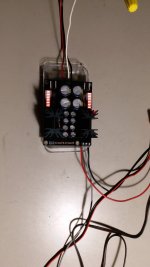
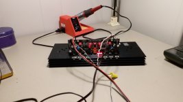
So I took a deep breath and connect the single DCSTB to the DCG3, I must have check the whole thing 5 or 6 times to make sure the value/transistor orientation was correct. Then no smoke and the LED turn on. After 30 mins, both the DCSTB and DCG3 's heat sink were mildly warm. As mentioned in previous post, I am using a 15v transformer with dual output of 17.7 ac unloaded. I will leave it on for a few hrs. to make sure everything OK and then take it from there.
Attachments
Hi Salas,
Relay clicks, offset adjusted to about 1.2 mv on both channel with shorted input. I am not too fuzzy on dc at this moment as the whole thing is exposed and I understand it is temperature sensitive. Tomorrow I will feed a music signal through and listen through headphone, also I will order new J1,Q2,J1 for the non-working board. So you think its J1 that's short (post 6663).
Relay clicks, offset adjusted to about 1.2 mv on both channel with shorted input. I am not too fuzzy on dc at this moment as the whole thing is exposed and I understand it is temperature sensitive. Tomorrow I will feed a music signal through and listen through headphone, also I will order new J1,Q2,J1 for the non-working board. So you think its J1 that's short (post 6663).
Salas: DCSTB's J1 must have gone during the mishap that blew the fuses The uneven voltage situation started way before the fuse was blown, it was during the fiddling (disconnect/connect the transformer) that the center tap was connected loosely. Speaking of the fuse, I am using a 1A SB fuse for the mono DCSTB. After I fixed the non-working board, I will put back the proper fuse (.4A). That said, I can only find .5 A Slow Blow locally, is that acceptable?
I will measure the bias current later today. Thanks for the heads-up.
I will measure the bias current later today. Thanks for the heads-up.
As VolumeControl? It's a 10 turn?Bourns Precision ones? Like this
When unpowered the output relay defaults to mute which is to groundUhm...
I just opened my (unconnected) DCG3 and had a look on how to commence.
I thought I'd first inspect the connections and here we are: The HP-out is completely shorted on the board (wiring seems good). That is, HP L/HP R and both Gnd are all returning ~1.x Ohm ...
Should be acceptableAfter I fixed the non-working board, I will put back the proper fuse (.4A). That said, I can only find .5 A Slow Blow locally, is that acceptable?
Thank you, Salas!When unpowered the output relay defaults to mute which is to ground
If I conclude correctly, there’s nothing wrong with the HP out being shorted, and the line out not?
- Home
- Source & Line
- Analog Line Level
- Salas DCG3 preamp (line & headphone)