Hi Jim, did you read the circuit description in post number #47? I will add a link of it in post#1 also now.Current mirrors, Sziklai pair capacitor multipliers and DC servos, Oh My!! Lots of cool things for this amateur to learn about. Wonderful stuff.
Thanks
Jim
Hi Jim, did you read the circuit description in post number #47? I will add a link of it in post#1 also now.
Yes thanks. Printed that off with the circuit a few days ago and stared at it for quite awhile. I will do that again a few more times. I gain a little more understanding each time. My wife and the dog do worry about my mumbling while I'm doing it
All single ended and each stage pushed to it's linear best. A lovely design. Now I have been reading about the Sziklai pair capacitor multiplier. Had not hear of it before. Thanks for bringing my learning a number of steps along. I am thinking about building two. One for the main system and one to live by my chair for my headphones.
Jim
Hi Jim, if twenty simple diyers will end up with a better sound in their homes and more ideas in their heads with this one I am more than happy.
No joy having it on my rack listening exclusively in solitude while nobody knows. I would feel like the Dracula listening to organ music then 😀
No joy having it on my rack listening exclusively in solitude while nobody knows. I would feel like the Dracula listening to organ music then 😀
GB INFO BELOW
GB Thread started here.
http://www.diyaudio.com/forums/grou...s-dcg-3-dcstb-power-supplies.html#post4855022
GB Thread started here.
http://www.diyaudio.com/forums/grou...s-dcg-3-dcstb-power-supplies.html#post4855022
Great! 🙂
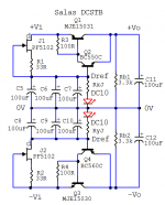
I know it could be a stupid quistion... but will it matter if i replace the capacitors C5 - C12 (100uF) with 220uF, and maybe use 4pcs 220uf instead of 8pcs. 100uF...
Quistion is, as i donno if something spectakular is about the design, giving the best performance etc...
Jesper.
I know it could be a stupid quistion... but will it matter if i replace the capacitors C5 - C12 (100uF) with 220uF, and maybe use 4pcs 220uf instead of 8pcs. 100uF...
Quistion is, as i donno if something spectakular is about the design, giving the best performance etc...
Jesper.
Attachments
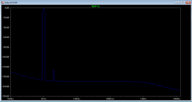
Salas, have you measured distortion for worst-case source impedance? I very much suspect it won't be quite as pretty as shown in the first post. Nothing that a cascode in the input stage couldn't fix, of course - preferably the bootstrapped variety, as we're talking reasonably high CM levels.
Salas, have you measured distortion for worst-case source impedance? I very much suspect it won't be quite as pretty as shown in the first post. Nothing that a cascode in the input stage couldn't fix, of course - preferably the bootstrapped variety, as we're talking reasonably high CM levels.
Hi, those plots were with the 20K pot at half (that's the worst case bandwidth point). I did also measure with no pot or the pot at max while controlling input level from the Arta generator's digital level only with no odd indications. I will have to measure my audio card box's analogue outputs source impedance when able to also inform you what it adds because its Zo is not stated in its manual.
The R1 3.3K input filter series element will be always there adding to any original source impedance though.
With that same equipment and methods I had also tried input stage cascoding when breadboarding various ideas and it made no real THD difference. Second stage cascoding and higher rails did.
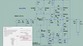
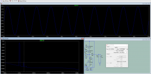
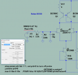
At the moment I can also show you simulation FFTs with ideal zero source impedance signal generator or with hiZo value added in LTspice. Seems nicer than with real life active parts and layouts to me for 8.63V pk-pk output across 10k/100pF but can't check such dbV with a pc card. The simulator should have at least shown something wrong with zero signal source impedance if instability was there waiting to happen. The real oscilloscope didn't too. Sims are also good with much Z (extra series with the signal) at comparable signal level region to the measured plots. Although I found it 7-10dB worse in real life with such Yfs class input JFETs at such levels.
Attachments
Great! 🙂
I know it could be a stupid quistion... but will it matter if i replace the capacitors C5 - C12 (100uF) with 220uF, and maybe use 4pcs 220uf instead of 8pcs. 100uF...
Quistion is, as i donno if something spectakular is about the design, giving the best performance etc...
Jesper.
Those capacitors were chosen to be slim enough for placement between the sinks for the given boards width restriction. And to achieve better spec than using a single equivalent value unit also. So three in parallel are still dividing their ESR & ESL better than two. But its not a big deal using less if keeping with good unit specs anyway.
Those capacitors were chosen to be slim enough for placement between the sinks for the given boards width restriction. And to achieve better spec than using a single equivalent value unit also. So three in parallel are still dividing their ESR & ESL better than two. But its not a big deal using less if keeping with good unit specs anyway.
Ahhh 😛 I think i still learn everyday 😎 three in parallel are still dividing their ESR & ESL better than two
Did not have this in mind...
-Thanks.
Jesper.
Hi Salas! Would you consider replacing the DC10EWA biasing LED with a TL431CLP? Would save board space and has fantastic specs.
No, its still noisier vs using LEDS. Also the rails have nominal value here. Since the DCG3 is not changing offset with non precisely symmetric supplies, there goes the adjustable benefit of that chip as well. If LM329s were adding to my target voltage I would have used those instead which are much better spec than the TL. But they don't.
Somewhere around page 5 or so of this thread someone asked about using this circuit in balanced format. That would of course mean that two of the DCG3 boards would be needed. Would you use one DCSTB board with one half feeding each DCG3 or is there a more tricked out approach?
Also, could you share your opinion whether you feel that a balanced differential output from the DCG3 may or may not sound subjectively better than the SE version. I am wondering about how the harmonics will pan out in balanced.
Thanks Salas.
nash
Also, could you share your opinion whether you feel that a balanced differential output from the DCG3 may or may not sound subjectively better than the SE version. I am wondering about how the harmonics will pan out in balanced.
Thanks Salas.
nash
Yes it could be done that way with DCSTB or BIB. Thought of eight rails PSUs and four transformers on the other hand is like we start to get into a megastructures fascination.
Balanced signal transfer is about canceling common mode noise interference its not like push pull circuitry doing out the even distortion harmonics. You pass two inverted phases of the same full signal not two halves of it reconstructed at the output. It would sound better in a true balanced system from source to speakers I would guess because not compromising its architecture. But making it balanced for the sake of it if there is no buzz or hiss and the apparent resolution is high its just more circuitry. If it was an MC preamp I would tell you that there would be +3dB more circuit noise for balanced also and there counts because 1000x gain but at 3x here its not interesting.
Balanced signal transfer is about canceling common mode noise interference its not like push pull circuitry doing out the even distortion harmonics. You pass two inverted phases of the same full signal not two halves of it reconstructed at the output. It would sound better in a true balanced system from source to speakers I would guess because not compromising its architecture. But making it balanced for the sake of it if there is no buzz or hiss and the apparent resolution is high its just more circuitry. If it was an MC preamp I would tell you that there would be +3dB more circuit noise for balanced also and there counts because 1000x gain but at 3x here its not interesting.
Balanced connection is the short form version of balance impedance connection.
It's the impedances that need to be balanced.
The drive voltages on the two signal lines can be anywhere, even zero volts and the connection will still be balanced impedance.
As stated in post257, balanced impedance connections are used to improve tolerance to interference.
It's the impedances that need to be balanced.
The drive voltages on the two signal lines can be anywhere, even zero volts and the connection will still be balanced impedance.
As stated in post257, balanced impedance connections are used to improve tolerance to interference.
It was me! My query was about using DCG3 as a line stage in my allready balanced system which would bring all the benefits described by Salas and Andrew. But this can't be achieved with two separeted boards running in parallel. It must be common tails (sorry I' m a tube man!). Since DCG3 is to be admired for it's performance, it will enter the system in it's SE glory!Somewhere around page 5 or so of this thread someone asked about using this circuit in balanced format. That would of course mean that two of the DCG3 boards would be needed. Would you use one DCSTB board with one half feeding each DCG3 or is there a more tricked out approach?
Also, could you share your opinion whether you feel that a balanced differential output from the DCG3 may or may not sound subjectively better than the SE version. I am wondering about how the harmonics will pan out in balanced.
Thanks Salas.
nash
It would sound better in a true balanced system from source to speakers I would guess because not compromising its architecture.
That indeed is my question. Whether the architecture using two DCG3 boards with true balanced differential source and true balanced differential power amp could be expected to sound better as opposed to using each of the same components in their SE mode with SE DCG3? I realize that balanced lines are correctly termed balanced impedance connections with their attendant benefits.
nash
- Home
- Source & Line
- Analog Line Level
- Salas DCG3 preamp (line & headphone)