Thank you Salas & Tea-Bag.
I think I have it figured together. I might have some questions soon and hopefully NOT problems.
this build looks to be 'by the book'.
I matched x2 two ohms 1 watt resistors for headphone out RZJ. 😱 Everybody else is dropping jumpers there.
I sanded my LEDs to fit them side by side. Ha 🙂 Yes, sand paper.
Cc & Cb are on the underside of the circuit board.
The BC transistors are hfe matched exact to 398 as per my AtMega Tester
The seller in China said the uPA68Hs were real and gave me his word. The quad of the FETs inside measures perfectly and all identical. If they don't play well or act up in the circuit, I will swap out for the LSK389s.
R6 gain resistors are 820 ohms for over 2x gain setting, under 3x.
I didn't have silver mica for the 10pf but I did have some nice COGs. I used them prior to great success in other amps and preamps. Low ESR very tight tolerance when sorted. I may switch them to mica later...
R10 bias is 8.2 ohms running on the hot side perhaps 130mA-ish. I'll measure later...soon...
I'm actually excited about this build. It bypassed every other project I had on the table. It took me 3 or 4 weeks to get it together. I think the enclosures and power supplies will be ready soon(it's all here beside my desk). I might have some questions and problems with the bias and heat but I got to fire it up 1st and see what time it is, then proceed to finer details. Could be a fireworks show for all I know. Ha.


Cheers.
I think I have it figured together. I might have some questions soon and hopefully NOT problems.
this build looks to be 'by the book'.
I matched x2 two ohms 1 watt resistors for headphone out RZJ. 😱 Everybody else is dropping jumpers there.
I sanded my LEDs to fit them side by side. Ha 🙂 Yes, sand paper.
Cc & Cb are on the underside of the circuit board.
The BC transistors are hfe matched exact to 398 as per my AtMega Tester
The seller in China said the uPA68Hs were real and gave me his word. The quad of the FETs inside measures perfectly and all identical. If they don't play well or act up in the circuit, I will swap out for the LSK389s.
R6 gain resistors are 820 ohms for over 2x gain setting, under 3x.
I didn't have silver mica for the 10pf but I did have some nice COGs. I used them prior to great success in other amps and preamps. Low ESR very tight tolerance when sorted. I may switch them to mica later...
R10 bias is 8.2 ohms running on the hot side perhaps 130mA-ish. I'll measure later...soon...
I'm actually excited about this build. It bypassed every other project I had on the table. It took me 3 or 4 weeks to get it together. I think the enclosures and power supplies will be ready soon(it's all here beside my desk). I might have some questions and problems with the bias and heat but I got to fire it up 1st and see what time it is, then proceed to finer details. Could be a fireworks show for all I know. Ha.
Cheers.

Damn, I forgot that I pulled the 8.2s Ha!Why R10 bias
Thats good. Now I'm looking at 110mA to 120mA bias area with the big red 10s.
I'm getting old man, sorry.
I wanted to run it hotter but perhaps it is best I start with 120mA-ish.
I'll call it divine intervention.
Thanks for looking close. I was hoping for that.
Cheers
Gain will be (820/499)+1=x2.643 or 8.442dB in this case. Not sure about those slim "NEC" μPA68s though. Available slim ones used to have Singapore printed on them, not Japan. And only the embossed "N" logo, not the NEC brand print also. Lets hope they are OK too.R6 gain resistors are 820 ohms for over 2x gain setting, under 3x. ...The seller in China said the uPA68Hs were real and gave me his word. The quad of the FETs inside measures perfectly and all identical. If they don't play well or act up in the circuit, I will swap out for the LSK389s.
I have a pair of LSK389s with the purpose of doing an AB test for more than a year. I couldn't find a TO71 socket for easy swapping. Even having separate pin sockets results pins touching each other, if only there was more space between pcb holes.
It's the last Jfet I'd like to try after testing 2SK117, 2SK170 and the μPA68s. I'm enjoying 2SK117 at the moment, maybe I'll put back the μPA68s in future for another round.
It's the last Jfet I'd like to try after testing 2SK117, 2SK170 and the μPA68s. I'm enjoying 2SK117 at the moment, maybe I'll put back the μPA68s in future for another round.
I have been designing my own PCB for this great preamp. Can't wait to make it play!
I also made an SMPS power supply with LCLC filters and TPS7A47/33 regulators that supply the main board which has the extra pairs of regulators for each channel. (I needed dual-stage regs because of the heat dissipation).
It also has a ground loop breaker.
Resistors will be Vishay MELF.
Film capacitors will be Panasonic ECPU.
Opamp will be AD823, one per channel, with a properly terminated second unit.
I put a solder jumper for disconnecting the opamp - to set the potentiometer first
According to the reviews I chose uPA68H and BC327-40 semis.
I need to make one more board: ladder relay volume control and input and output management. It will have an ESP32-S3 MCU which will control the volume and output signal relays and show everything on the small OLED display. Will have a rotary encoder for controlling.
Everything should comfortably fit in the 200x220x52mm case.
I would appreciate a suggestion, critique, or anything that could improve the design.
Disclaimer: For personal use only.
'They' make tiny pins for this purpose. 'Micro sockets', 'header pins' and 'press pins' and all kinds if you can find the right words to search. Digikey stocks them as I have bought them there in the past.couldn't find a TO71 socket for easy swapping. Even having separate pin sockets results pins touching each other
Attachments
Hi, renderings look nice. Do you still use the voltage drop LEDs for the relay, or just a higher voltage relay? If you want to make it fancier you could add further reg chips for powering the input stage independently of the output stage. Can keep the input stage at +/-15V to +/- 17V and allow to the output stage +/- 20V or more for extra headroom and power with lower distortion when pushed, especially if for difficult headphones. Keeping an eye on output stage dissipation and sinking of course.I have been designing my own PCB for this great preamp. Can't wait to make it play!
I also made an SMPS power supply with LCLC filters and TPS7A47/33 regulators that supply the main board which has the extra pairs of regulators for each channel. (I needed dual-stage regs because of the heat dissipation).
It also has a ground loop breaker.
Resistors will be Vishay MELF.
Film capacitors will be Panasonic ECPU.
Opamp will be AD823, one per channel, with a properly terminated second unit.
I put a solder jumper for disconnecting the opamp - to set the potentiometer first
According to the reviews I chose uPA68H and BC327-40 semis.
I need to make one more board: ladder relay volume control and input and output management. It will have an ESP32-S3 MCU which will control the volume and output signal relays and show everything on the small OLED display. Will have a rotary encoder for controlling.
Everything should comfortably fit in the 200x220x52mm case.
I would appreciate a suggestion, critique, or anything that could improve the design.
Disclaimer: For personal use only.
Thanks! This is all rendered inside KiCad. No additional enhancement.Hi, renderings look nice. Do you still use the voltage drop LEDs for the relay, or just a higher voltage relay? If you want to make it fancier you could add further reg chips for powering the input stage independently of the output stage. Can keep the input stage at +/-15V to +/- 17V and allow to the output stage +/- 20V or more for extra headroom and power with lower distortion when pushed, especially if for difficult headphones. Keeping an eye on output stage dissipation and sinking of course.
24V relay was used (21.5V to power it - datasheet says it's ok) so no need for voltage drop. SMPS are 24V, the first stage regulates down to +-21.5V, and the second stage regulates down to +-17.5V. Voltages are chosen to keep LDOs power dissipation well under 1W.
Thanks for the suggestion! I wondered the same, to power the input stage separately, but in the end, it turned out too complicated. Unfortunately, I had to draw a line somewhere. Also, my 8 month old kid limited my budget 😀.
I will be using DCG3 with HD560S headphones (120ohm) and 100mA bias. Yes, I calculated everything for 150mA bias so I can change it if needed in the future.
Mosfets will be tied to an aluminum block (part of the case) which measures 220x52x6mm and it should radiate the heat out of the case.
Understood. Good luck with finishing it. Also don't forget to check that all rails will be oscillation free when finished by using the scope. For peace of mind, because modern chip regs can be too sensitive regarding layout and local decoupling.
Will do.Understood. Good luck with finishing it. Also don't forget to check that all rails will be oscillation free when finished by using the scope. For peace of mind, because modern chip regs can be too sensitive regarding layout and local decoupling.
Again, thanks a lot!
*Posts #1 #6,941-6,943 & #6,965 #6,967 #6,970 #7,014 are valid measurement references to compare if a build is fully performing, or why not, if even exceeding prior measurements a bit.
No unfortunately. I don't have the gear but would very much like to measure it.Will you be also fully measuring for FFT plots etc?
Some Croatian friends willing to help? I will buy beers😂
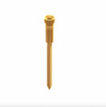
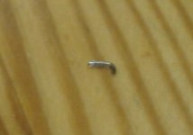
Nick, I've decided to do the final JFet testing, in order to have an easy swapping between them I've decided to put the AD823 in a more easy swapping base using headers. When I've desoldered it along with it's original base I've noticed a tiny wire (?) trapped in the base's legs.
So my question is there a way testing it before putting it back ?
Take note that before taking it out, I've measured dc offset and most of the time was hovering between +/- 3mV but over time it went up to 9mV and even more. Particularly when I was taking the needle off the record it went up +/- 25mV. Finally when I shut down the phono stage (USFP which of course has an output cap) it hit the -/+ 300mV DC resulting my power amp shutting down. I normally change input before doing such a thing but I'm curious especially now that I found this damned wire.
Attachments
To test an op amp in basic terms you can put it on a breadboard and first measure if its mA bias draw from PSU lines agrees with the datasheet. Then verify its offset spec vs datasheet. Configure it as a buffer with a wire between out & in- pins, apply say 2V DC to in+ and measure on out pin for mV DC difference vs 2V. We do also verify the slew rate with gen and scope sometimes but mainly when having doubts about originality. Re-adjust DCG3 for minimal own offset before putting back that specific one or another servo chip.
Thanks, Nick, for the informative answer, as always.
I've done these and the results:
For the test for DC offset, I've provided DC at input via a 1.285VDC battery and there is not a difference with output (1.285VDC) of course with (out) and (- in) pins connected together.
Current drown by opa powering it by a 9VDC battery is 4.8mA and by 12.3VDC regulator 7.2mA. Looking at the graphs it's little bit low (battery) and little bit high (reg) but I assume it passes the test (done with my Fluke 179) what do think Nick ?
Here is the new socket for AD823

Now it extends over the pcb and it's easy to pull it off and put it back not only for opa swapping but for JFet swapping too, remember you have to readjust DC offset each time (and pull out the opa doing so)

I've done these and the results:
For the test for DC offset, I've provided DC at input via a 1.285VDC battery and there is not a difference with output (1.285VDC) of course with (out) and (- in) pins connected together.
Current drown by opa powering it by a 9VDC battery is 4.8mA and by 12.3VDC regulator 7.2mA. Looking at the graphs it's little bit low (battery) and little bit high (reg) but I assume it passes the test (done with my Fluke 179) what do think Nick ?
Here is the new socket for AD823
Now it extends over the pcb and it's easy to pull it off and put it back not only for opa swapping but for JFet swapping too, remember you have to readjust DC offset each time (and pull out the opa doing so)
7.2mA seems like an experimental error? Datasheet states 5mA nominal to 5.6mA max quiescent between 3V to 36V single supply (just insert mAmeter between +rail and the opamp's +Vs pin). AD823 can work both on single or split supply. The Fluke 179 is reliable but with just 6000 counts its difficult for you to discern little offset at unity gain.
You know what? Set it for gain, something around x100 so it amplifies and its easier to read. The output offset tells the input offset when divided by the gain.
A nice video about DC offset in op-amps
You know what? Set it for gain, something around x100 so it amplifies and its easier to read. The output offset tells the input offset when divided by the gain.
A nice video about DC offset in op-amps
- Home
- Source & Line
- Analog Line Level
- Salas DCG3 preamp (line & headphone)