
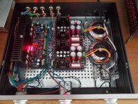
I'm laying out DCG3, FSP and 2x6-24 crossovers in one 2U chassis. All Transformers and PSU's in a second 2U chassis
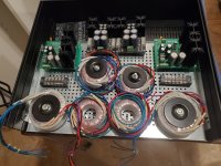
I'm having space issues with 6 x50va transformers and psu's in one 2U
Any issues if I used 2x30va Antek for DCG3 and 2x30va Antek for FSP. - This would work out and be a nicely filled chassis.
If necessary, I would step up to a 3U but my preference is to stick with the 2U
Thanks!
I'm having space issues with 6 x50va transformers and psu's in one 2U
Any issues if I used 2x30va Antek for DCG3 and 2x30va Antek for FSP. - This would work out and be a nicely filled chassis.
If necessary, I would step up to a 3U but my preference is to stick with the 2U
Thanks!
Last edited:
Both had worked nicely with good quality 30VA toroids in build examples that space was at a premium. Just avoid encapsulated EI ones because at 30VA they do get warm enough for a DCG3.
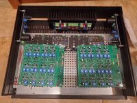
Finally changed the two led bars and now all leds light up nicely. Output now is:
Left Ch: -17.5, +17.1
Right Ch: -16.9, +17.4
I notice a larger diff between positive and negative rails than before. Is this ok?
Left Ch: -17.5, +17.1
Right Ch: -16.9, +17.4
I notice a larger diff between positive and negative rails than before. Is this ok?
*There are the R1 R2 33R setting current for J1 J2 which finally runs through the LEDs. Check mV drop between each 33R resistor's own legs to see if about the same. Just to confirm no J was also gone when your original mishap crippled those two LED bars.
Left channel: Both R1 and R2 4.9mV
Right channel: Both R1 and R2 4.3 mV
Pretty close it seems!
Right channel: Both R1 and R2 4.3 mV
Pretty close it seems!
Close is good but the figures seem tiny. Your Led bars looked well lit and the rail voltages appropriate. For 5mA via 33Ω we should read 0.165V between its ends.
Now that I remember it, I thought I was missing the 33R resistors, but later saw that teabag had included 1R in their place in my kit, so I used them. Does that make sense? That way at least one channel is about 5mA, the other one a little lower. The above numbers are with 1R values in R1, R2 in both channels.
Last edited:
Yes that's making again 4-5mA normal spec constant current coming from the Jfets to the Leds. Maybe you swapped the 33Ω R1 R2 with RxJ RyJ.
No, these are also 1R, there were not 33R at all, tea had the correct resistor values for the supplied J1/J2. That's tea for us, taking care of all the details!
Its true that 33R is for PF5102 samples with >>5mA IDSS so to moderate them. If the samples are naturally close to 5mA by themselves then 1Ω is preferred to just close the circuit and as a test point.
He had once asked me what to do if with lower than average at the time J1 J2 IDSS samples. But I didn't remember when you talked about 1Ω R1 R2 that he was planning to systematically go into such matching detail level in the actual sets.That's tea for us, taking care of all the details!

Wasn't it originally planned as a combination box with electronic crossovers & phono?A 3 day old DCG3.
You opted for simply stereo preamp build and you decided to put the rest of stuff in a different box?
I'm laying out the combo boxes as well for a few 3way active systems
The plan is for 2 sets with 3way xover, phono and DCG3
Also one more set later with Xover, dac and dcg3.
50 va trafos are little large so 4 will be 30va. Also want to add a Soft Start board..
And the DCG3 on post 6916 I plan to build a 2 way xover in a 1u galaxy matching the width
I'll need a few more dcg3's from the next groupbuy
Attachments
Last edited:
- Home
- Source & Line
- Analog Line Level
- Salas DCG3 preamp (line & headphone)