But now I am curious.
I forgot to mention that measuring slew rate in doubtful origin op-amps is a good way to confirm if they are fakes or not. I had done this for enough types and I once caught ten legit looking 5532s for giving 6V/uSec instead of 9V/uSec. Although the pulse shape was akin to original samples. Some times they don't refer to a symmetrical 10V square but to a 5V positive going pulse.
That, and how many mA Icc they consume when idling is another good checkpoint. The same op-amps (probably not a relabeled different type but altered-performance silicon mask copies) measured less than spec Icc too.
Slew has to do with the internal compensation capacitance, mainly in unity gain stable types, and to other design factors like how much bias current is available to their output stage. So Icc is related.
In places where op-amps are used by the hundreds like in many channels analog mixing desks, the combined Icc consumption is a serious engineering concern for temperature rise and PSU bulk. Also in battery operated gear where every mA counts.
Hello Salas,
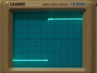
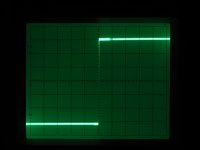
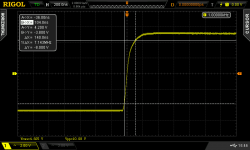
RE Post #5899, #5901... I am totally unable to measure slew rate. Evidently my 50MHz analog scope cannot keep up with the DCG3. Because it is an analog scope, it is difficult to position the trace (horizontally) exactly where needed: just touching the knob with the lightest touch sends the trace way off center. I used 100mv p-p signal, and was unable to visually see anything at all. I switched to 1V p-p and can see just a suggestion of delay, so small as to be insignificant and immeasurable. See attached photos. I'd be curious to know if you've measured slew and what you measured. I would not be at all surprised if technique is at fault. Here is best I could manage:
Input: 1KHz, 1V p-p
Vert: 0.5V/div
Horiz: 100ns/div
I still think (1) the uPA68 is a pretty amazing part, even the fake/imitation/non-NEC parts I am using, and (2) am still very pleased with sound quality.
Attachments
Hi,
Yours is at its fastest because straight in without a volume pot. I had measured it back when dcg3 was introduced. On my 200MHz DS2000 series Rigol scope, but I can't remember the figure. I will have to disconnect it and uninstall it from the rack to measure the SR again. To be almost like yours I will have to set volume at max. I will let you know. Unless somebody else beats me to the punch measuring it on his own DCG3 meanwhile.
Yours is at its fastest because straight in without a volume pot. I had measured it back when dcg3 was introduced. On my 200MHz DS2000 series Rigol scope, but I can't remember the figure. I will have to disconnect it and uninstall it from the rack to measure the SR again. To be almost like yours I will have to set volume at max. I will let you know. Unless somebody else beats me to the punch measuring it on his own DCG3 meanwhile.
I will have to disconnect it and uninstall it from the rack to measure the SR again.
Please do not make any special effort. Knowing what the number is, 10V/us, or 50V/us, or whatever, would not change a thing. And to be 100% honest, well, it's just a number. It's the sound that counts.
Let's just say "excellent" on all counts and call it a day.
No worries, we got lucky. Coincidentally a friend dropped me a standard build DCG3 along a Nakamichi deck to check today. Here we go...
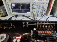
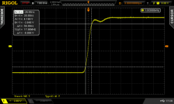
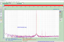
Slew Rate=dv/dt or ΔΥ/ΔΧ on those cursors. 10Vpp large signal domain 10%-90% is 8V. If allowed to hit the volume pot end stops its very fast. It slews that in 56nS time. Or in 0.056uS because 1nS is 0.001uS. 8/0.056=143V/uS (!).
OK, because the Siglent 2042X generator has its own less than perfectly muted corner peak and not sure about reflections in the thin audio cable line and BNC adapter, I then held it back just a bit from absolute max for a tiny pot track damping to iron out the corner. 140nS to reach 8V now. 8/0.14=57V/uS. Alright, lets call that max before engaging the afterburner. 😎
Attachments
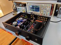
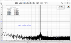
Before I return this DCG3, something notable. Between the MOTU M2's self loop in single ended mode or with the preamp inserted, no real difference. 1.3dB better THD with the preamp looped-in according to the software but it must be random. Noise floor bottom level slightly different due to the attenuators settings. This is just a build guide standard preamp with six way In-Selector board, DCSTB PSU, thin coax internal wiring, and a TKD 2CP-2511 20K pot for volume control. The one pictured in the post above.
Good enough technical performance not to be called intrusive. On quick A/B (as fast as plugging and unplugging the jack between units) sound on Sennheiser HD 600 was instantly better via the preamp's headphones output than directly from the MOTU's HP out.
Good enough technical performance not to be called intrusive. On quick A/B (as fast as plugging and unplugging the jack between units) sound on Sennheiser HD 600 was instantly better via the preamp's headphones output than directly from the MOTU's HP out.
Attachments

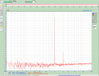
When the MOTU M2 needs true two phase balanced drive to be at its best for second harmonic, my other interface the EMU Tracker Pre which simply has balanced impedance architecture achieves its best THD in single ended mode too. Its a noisier old model, mainly below 100Hz and for supersonic hash, but handier with single ended connections performance. The MOTU as almost all new generation models needs a transparent SE to Balanced converter to match its SE & BAL THD readings. I posted those charts in the past but for completeness here they are again. EMU loop alone (one channel) and with my own standard DCG3 inserted (stereo).
Attachments
Hey fine people! Happy Holidays.
Little trouble in paradise with the DCG3... getting maybe 30% of audible output from the left channel... Because our room is funky and the speakers do an amazing job of disappearing...we didn't immediately notice it... but after swapping amps etc the issue followed the cables. I'm seeing normal measurements from the PSU, and across R10, mA right in the zone for 10R, both channels... Any ideas of where to hunt?
Salas, I have skills, but assume I know 1/100th of you (or less) as far as electronics are concerned! Ha.
Hello, and Merry Christmas to all!
Take it to the bench first. Apply 1kHz 1V RMS sine from a generator on both channels of its first input, set the volume attenuator at 50% and track the test signal with the oscilloscope's probe from input connector to output connector all the way through. Comparing it between channels. Try to find the spot where significant signal is lost vs the stronger channel. That will give clues to what is locally wrong. If everything seems normal try the next input. Can be a connection, a bad solder joint, a relay, the attenuator, a broken transistor, anything. Haven't had this occasion reported before on a dcg3 to can give you a most likely suspect location info.
Take it to the bench first. Apply 1kHz 1V RMS sine from a generator on both channels of its first input, set the volume attenuator at 50% and track the test signal with the oscilloscope's probe from input connector to output connector all the way through. Comparing it between channels. Try to find the spot where significant signal is lost vs the stronger channel. That will give clues to what is locally wrong. If everything seems normal try the next input. Can be a connection, a bad solder joint, a relay, the attenuator, a broken transistor, anything. Haven't had this occasion reported before on a dcg3 to can give you a most likely suspect location info.
Oh man... there was about to be some insane learning...I have a generator that my uncle gave me... but I have no idea how to use it! (yet). However... When it was on the bench and I was poking around I found a bad/partial connection to the Muses! Made up some new wires... and we are back in business!!! Thanks for the holiday response/support Salas—I'm sure you had better things to do—but you got me thinking, and my instinct was it was something simple—which it was!
Congratulations for finding the bad spot. A PC can run a software generator also. Or an older phone with headphone jack can be used. There are gen apps. For simple signal in the audio range. Don't expect clean square waves or low noise from such. Still handy for troubleshooting. Below 500Hz even a narrow response DMM in AC mode can track the signal route when not having a scope. Can't show a waveform but it can report its RMS level. Apply a fairly large test signal to help the DMM's sensitivity.
Hi here fellow diy'er 🙂
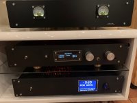
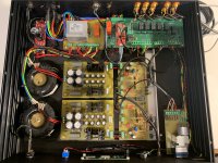
I finally finished my rebuild of my 2016 DCG3 build.
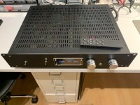
The preamplifier have been here for 5+ year's now, and i thought i would put it into a somewhat bigger chassis along with something i have been wanting to do for a long time, but never did, before now that is.
While i was at it i changed the gain from X2 to X3, checking everything was good (bias + DC on output), both before and after the change.
Nothing to adjust, so really stable design here... Thanks Salas.
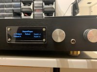
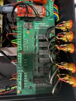
I have designed an (amateur like) ESP32 input selector, remote-controller, motordriver for alps-motorpot, IR remote, SSD1322 oled etc... and IEC230vac output for poweramp., to have an delayed power sequence.
The PCB was created in Germany and is reel good quality i must say. - I use an ESP32 with external antenna for bluetooth if i ever decides to use that.
Well everything is working as expected, except that i need to do some smaller codechange duo that our TV-remote is interfering a bit with the remote i use for the DCG-3.
Jesper.
I finally finished my rebuild of my 2016 DCG3 build.
The preamplifier have been here for 5+ year's now, and i thought i would put it into a somewhat bigger chassis along with something i have been wanting to do for a long time, but never did, before now that is.
While i was at it i changed the gain from X2 to X3, checking everything was good (bias + DC on output), both before and after the change.
Nothing to adjust, so really stable design here... Thanks Salas.
I have designed an (amateur like) ESP32 input selector, remote-controller, motordriver for alps-motorpot, IR remote, SSD1322 oled etc... and IEC230vac output for poweramp., to have an delayed power sequence.
The PCB was created in Germany and is reel good quality i must say. - I use an ESP32 with external antenna for bluetooth if i ever decides to use that.
Well everything is working as expected, except that i need to do some smaller codechange duo that our TV-remote is interfering a bit with the remote i use for the DCG-3.
Jesper.
Attachments

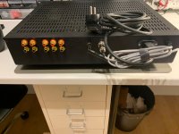

LykkeTech® 🙂 Great work Jesper! Nice wiring and the way you have mounted the screen window adds points I think!
I'm about to start building a dcg-3 with an i-select and motorised TKD 2cp-2511 volume pot. It will replace the Mezmerize I've been using alongside the Aleph power amp. I'm keen on having the option to use headphones for late night listening and want to know if the output to power amp is cut when a headphone us plugged in?
No it's not cut. The HP and Line outputs are separate and always active. You could add a cut switch at the line output.
Or just don't turn the power amp on! 🙄 doh!No it's not cut. The HP and Line outputs are separate and always active. You could add a cut switch at the line output.
- Home
- Source & Line
- Analog Line Level
- Salas DCG3 preamp (line & headphone)