Goose the DCG3's input with a non-inverting OPA1611 !!!
Hello Salas! I've had your DCG3 preamp boards in my system for a couple of years and liked it, but not quite as much as my tube/Fet hybrid ARC PS2 preamp in terms of bandwidth (detail and liveliness). A later mod of the preamp with your boards included an OPA1611 non-inverting opamp set for 2x voltage gain and man your DCG3 boards sing! I put these opamps after the volume pot for buffering purposes and discovered that your DCG3 does better with an opamp that can decently drive its input transistor. Now that combo dishes out tons of detail when playing hi rez FLAC files. I dig this opamp because of its cascode input stage, which gives it the huge bandwidth. Best.
Hello Salas! I've had your DCG3 preamp boards in my system for a couple of years and liked it, but not quite as much as my tube/Fet hybrid ARC PS2 preamp in terms of bandwidth (detail and liveliness). A later mod of the preamp with your boards included an OPA1611 non-inverting opamp set for 2x voltage gain and man your DCG3 boards sing! I put these opamps after the volume pot for buffering purposes and discovered that your DCG3 does better with an opamp that can decently drive its input transistor. Now that combo dishes out tons of detail when playing hi rez FLAC files. I dig this opamp because of its cascode input stage, which gives it the huge bandwidth. Best.
OPA1611 is technically transparent, nice it helps you find what sound you need from DCG3. Ever tried the preamp with native 6X gain? That's what it now totals together with the OPA 2X. Could be you mainly needed this extra kind of gain for your system? Liking how its now buffered is what counts anyway. What value and type is the volume pot you use?
A typical DCG3 set at 3X internally if with a buffer upfront hits at least 2MHZ bandwidth. 600kHz-1MHz without it. Depends on vol pot value and parasitic capacitance up to its line input pads. See post #20 for scope shots with 20kHz and 50kHz squares & 20k pot. Going twice as fast rise time could possibly make it sound too incisive in some other systems though. Or precarious for opening the door wider to RFI interference if strongly present. We even had a couple of builders with kind of cold room curve resulting speakers that HF felt better upon using the slower 50k pot value permitted in the schematic.
Wherever a tweak works right its good though. You had a need for speed, and you got it. DCG3 did not deny or it reared an ugly head. To the contrary. Its an easy add-on tweak for anyone feeling his system needs to go more in that way. Thanks for letting us know your experience. Happy listening & regards.
My notes indicate that the DCG3 gain is set for 5.3x. Multiply the gains and we see that I'm running at 10.3 x voltage gain! Whoa! She's running hot!. Not heat, but gain of course. The volume pot is a DACT CT-2 (50Kohm, 24 step, hard stopped at 16 steps right now). I can run the volume pot at 50% without feeling pain, and instead feel that it sounds very natural. I should consult younger ears to see if this is ridiculously loud. This preamp feeds a biamped system. A Marsh 400A feeds the midrange and tweeter drivers of Paradigm 100 Studio Monitors (circa late 90's). An Adcom 5800 is driving the woofers. Both amps measure 25X voltage gain on the bench.
BTW, the highish gains and the addition of the OPA1611's where a result of other complexities of the overall preamp chassis. I've included an IN/OUT switchable Linkwitz electronic crossover board to see if keeping out of band signals from entering the two amps yields an audible benefit. So far, setting if for IN yields a slight benefit. The Crossover is at 275Hz, the indicated crossover Sterophile test side bar revealed.
I'd like to add for your readers the observation that the Paragdigms bandwidth increased mightily when I replaced the stock non-polar aluminum caps in the speakers circuit with spendy Jantzen Audio Superior Z-cap series parts. Without replacing run of the mill caps with good one's your system cannot reach its full potential.
Thank you Mr. Salas for you contribution to the art and science of audio!
S.
You are welcome. Using that much internal gain and a 50k pot steals loop feedback and input filters lower at the same time so in your case bandwidth has shortened to about 400kHz. Thus your input buffering with an OPA1611 after the pot idea clearly makes sense. Restores the lost speed.
Nice thing is although you manipulated the standard configuration enough, DCG3 only returned heaps of detail without bursting into instability.
A cool tweak acceptance margin by the circuit itself and certainly a good implementation job from your side.
Any photos you may share from the personalized preamp config and maybe from the system as a whole?
At any rate, very happy so far.
Had a chance for lengthier auditions since?
Had a chance for lengthier auditions since?
I've actually got it back in my workshop now. I noticed that the channel balance was a bit off. When I hooked up the scope to try to figure out where the levels were off, I found that I was getting oscillation on the DCG3 outputs. I was in such a rush to hear what it sounded like that I hadn't bothered to do this before 😀. I haven't had time to follow up to figure out what's going on but it's on all four outputs (both channels of both boards).
One of the modifications I made was to connect R7 between the two channels on the same board instead of to ground (e.g. gate of J2 from one channel connected through a resistor to the other J2 gate on the same board) since these two channels are acting as the positive and negative phase of the same signal. This may be contributing to the instability, so I'm thinking the first step is to change this to your original design.
I also believe that Khozmo built my attenuator boards with shunt resistors designed for a 10K series resistor instead of the 5K I asked for, since the output is too high. So I will swap these out as well. I seem to remember reading something about the DCG3 being sensitive to input load impedance. Is this something I should be looking at?
Another thing I was planning to do is to make sure all the enclosure panels were electrically connected, and to add some shielding between the DC power input connections and the attenuator (all the DC input wires run under the attenuator to connect to the UBibs).
I'd appreciate any other ideas you might have. I don't have much in the way of test gear - just multimeters and a cheap digital scope. I can use my DAC to create a fairly clean sine wave which is what I have been using to test.
Thanks,
Jay
Re: Oscillation
R7 Configure it as standard first.
Does it do the same with and without the extra circuits you use?
Re: attn
5k attenuator output impedance works with the preamp's input like a 20k series pot that seems to be the preferred reference value here. The higher this impedance the slower the preamp. Sounding more rounded. 50k series pot presents 12.5k max Zo for instance (mid point worst case).
I got one of the two boards updated, replacing the combined R7 with separate resistors for each of the two sides, and the oscillation went away. 🙂
I hope to find time tomorrow to do the other board.
I hope to find time tomorrow to do the other board.
Salas, you said a while back regarding using the amp in an opamp configuration for dac output stage MAYBE could work, but had to be set at gain of at least 2 to be stable.
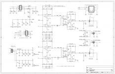
the schematic is from member «Iancanada» output stage for sabre es9038q2m dac.
So if i would replace last opamp with «DCG3 bare cell» circuit, should i remove the low pass filter caps (c6,c11,c17,c26), replace it with something that sets the pole in accordance to DCG3 build guide, and make sure the voltage divider that set the gain (390R+200R) is 2 and not 1,5 or so...?
Don't want to be really off-topic, so please respond as you see fit, of course. I understand this goes beyond the original intention of the circuit.
Has to be utilized like an op-amp cell with + - inputs, meaning open access to its feedback return node. Following established balanced to SE op-amp arrangements as described in technical articles.
I don't know if it would react badly or not, never had a reason to try it like that. In such a case I would have kept the rearranged networks impedance as low as in its standard application at least.
the schematic is from member «Iancanada» output stage for sabre es9038q2m dac.
So if i would replace last opamp with «DCG3 bare cell» circuit, should i remove the low pass filter caps (c6,c11,c17,c26), replace it with something that sets the pole in accordance to DCG3 build guide, and make sure the voltage divider that set the gain (390R+200R) is 2 and not 1,5 or so...?
Don't want to be really off-topic, so please respond as you see fit, of course. I understand this goes beyond the original intention of the circuit.
Attachments
Last edited:
...Sorry i forgot: the filter could be added after the output stage with a simple RC network if it's left out. For the DC servo, not sure if it's needed because the opamp cell looks like it has it's +- input dc voltage fixed at a value decided by the divider to ground.
Again, i know this is a bit experimental, but i'd be curious to see the outcome!
Again, i know this is a bit experimental, but i'd be curious to see the outcome!
I got one of the two boards updated, replacing the combined R7 with separate resistors for each of the two sides, and the oscillation went away. 🙂
I hope to find time tomorrow to do the other board.
Joining the two R7 instead of to G did not work for me either. It increased the hum.
nash
Salas, you said a while back regarding using the amp in an opamp configuration for dac output stage MAYBE could work, but had to be set at gain of at least 2 to be stable.
the schematic is from member «Iancanada» output stage for sabre es9038q2m dac.
So if i would replace last opamp with «DCG3 bare cell» circuit, should i remove the low pass filter caps (c6,c11,c17,c26), replace it with something that sets the pole in accordance to DCG3 build guide, and make sure the voltage divider that set the gain (390R+200R) is 2 and not 1,5 or so...?
Don't want to be really off-topic, so please respond as you see fit, of course. I understand this goes beyond the original intention of the circuit.
Yes, some attempt along the thought lines you describe
Joining the two R7 instead of to G did not work for me either. It increased the hum.
nash
Yep. Live and learn. I was getting a high frequency oscillation. I didn't measure it, but probably hundreds of kilohertz or higher and fairly large voltage swings (significantly higher than the normal signal). After going back to separate R7 resistors, everything is good.
I also found a bad connection on one of the balanced input connections (the one I happened to be using) which was causing the channel imbalance. That's what I get for trying to solder semi-blind with the boards already in place to minimize wire lengths.
I also replaced the 5k series resistors in the attenuator with 10k which should make the range more useable.
Everything tested well on the bench and my preamp is buttoned back up and ready to go back into my main system tomorrow.
DCSTB Voltage In
Salas,
I've finished my DCG3 and DCSTB build, and I have a question regarding the DCSTB voltages.
I am using the build as a headphone amp, and am listening with a pair of (approx) 26R Denon D2000 headphones. I am using 6.8R resistors for R10, bias current approx 160mA.
I would like to use two small Antek 10VA transformers, as the small size fits nicely into the chassis I plan to use. With everything connected, and the amp warmed up, the transformers are delivering 20VDC into the Sziklai pairs, 17VDC out. VI was measured at the fuses
Question: is 3V headroom enough for the Sziklai pairs? I think it is, as the VBE for a Sziklai pair is only one VBE drop, leaving approx 2.3V margin. But perhaps I am missing something? Maybe the design calls for more and I'm just not seeing that, or something else I'm not aware of? I'd like to hear your thoughts before I finish the build and attach the covers.
Mike
Mike hi,
3V headroom for the Sziklai pairs is enough to do their work. I just like giving them bit more slack like 5V because they could do little better, mainly for interjunction capacitance. On the other hand, less headroom is good for their dissipation. In your example with 160mA I would be tempted to factor heavier the latter. Especially if the chassis is rather constricted.
3V headroom for the Sziklai pairs is enough to do their work. I just like giving them bit more slack like 5V because they could do little better, mainly for interjunction capacitance. On the other hand, less headroom is good for their dissipation. In your example with 160mA I would be tempted to factor heavier the latter. Especially if the chassis is rather constricted.
Attachments
Ahh... there is more that I did not understand. Thanks for that.3V headroom for the Sziklai pairs is enough to do their work. I just like giving them bit more slack like 5V because they could do little better, mainly for interjunction capacitance.
I must admit I was surprised with lack of heat on DCSTB heat sinks. Warm to touch, but no more, room temperature. But, the math says 3V drop x 160mA is approx 0.5W, very little.
As for "a little better", I wonder if that is possible? This amp sounds amazingly good as is, even with only 3V headroom. I am very, very impressed with the sound quality. There are certain songs/recordings that simply come alive with this amp, I feel as if I am listening to a living, breathing thing:
Yes "Close to the Edge" (all of it)
Steely Dan "Babylon Sisters"
Buddy Guy "Blues No More"
Eric Gales "Help Yourself"
Johnny Winter "Who Do You Love"
Stones "Can't You Hear Me Knockin"
Leslie West "Fade Into You"
Trower "Secret Place"
Tinsley Ellis "Autumn Run"
Pink Floyd "Marooned"
And the best part? I'm just getting started. This will keep my busy for a long, long time.
My sincere thanks for such a wonderful design, so musical, so pleasant to listen to. And also to Tea for making boards available.
You are welcome. Nice that you like it.  Fun fact is I designed it as a line preamp with long cables driving capability in mind. Its headphones output was not a main target
  just a thing it could eventually also do.
Little better means refinements here and there from overspending in space heat and money.
Big transformers, wider voltage margins, huge vol pots, harder working PSU, or even shunt PSU, all leading to big spending and big chassis. You know, the usual over-engineering bugs we tend to entertain in builds.
I don't think >3V across is a priority thing to can clearly pick alone. Only watch the local power grid variations if any, not to give less than 2.5V DCSTB headroom.
For you, if you will get the tweak desire bug, I recommend tasting different semis flavors. So you can listen to something different but tiny and cool without mutating your chassis.
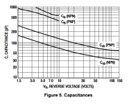
For J1-J2 maybe a more scarce and expensive NOS part than the NEC uPA68H itself. Say a nowadays ridiculously expensive Toshiba 2SK170 quartert within a rather slack 1mA IDSS matching tolerance. Rolling JFET types objectively affects things due to their differences in transconductance and internal capacitance.
Fun fact is I designed it as a line preamp with long cables driving capability in mind. Its headphones output was not a main target just a thing it could eventually also do.Little better means refinements here and there from overspending in space heat and money.
Big transformers, wider voltage margins, huge vol pots, harder working PSU, or even shunt PSU, all leading to big spending and big chassis. You know, the usual over-engineering bugs we tend to entertain in builds.
I don't think >3V across is a priority thing to can clearly pick alone. Only watch the local power grid variations if any, not to give less than 2.5V DCSTB headroom.
For you, if you will get the tweak desire bug, I recommend tasting different semis flavors. So you can listen to something different but tiny and cool without mutating your chassis.
For J1-J2 maybe a more scarce and expensive NOS part than the NEC uPA68H itself. Say a nowadays ridiculously expensive Toshiba 2SK170 quartert within a rather slack 1mA IDSS matching tolerance. Rolling JFET types objectively affects things due to their differences in transconductance and internal capacitance.
- Home
- Source & Line
- Analog Line Level
- Salas DCG3 preamp (line & headphone)