So the new version v1.03 has outputs grounded if powered off..... It might be the perfect solution..... Will hack the board and let you know .
I should have said, following equipment inputs shorted to gnd before power on 🙂
The DCG3 outputs are never shorted..
The DCG3 outputs are never shorted..
I apologise if this has been asked before but which if any of the transistors need to be matched to make the Preamp? I was hoping to build it over Christmas if I get the free time.
Seasons greetings to all
Ian
Seasons greetings to all
Ian
Wiring volume pot with Salas input selector module
Having a bit of a brain cramp figuring proper wiring of my ladder volume pot. My confusion is ironically being caused by the simplification this board allows! I am using the same ladder volume pot I used in my BA3 preamp.
Below is the wiring diagram I used for the same volume pot in my BA3 front end preamp.
I am I correct in assuming all I need to wire is what have labeled as ground from "From selector" to proper ground holes for left and right
pads on the Alps volume pot footprint on Salas selector board, and the wires I have labeled as "From selector" to the proper pads on the alps volume pot foot print on the Salas selector board....
Then the wires I have labeled as "out to amp board" to the other pair of pads on the Alps volume pot foot print on Salas selector board, and those wires ground to the same ground holes the "from selector grounds are going to?
Something just doesnt seem right about the way I am showing here, I think I am being thrown by the fact the "output" to amp is on the board, not the pot itself....
Clarity much appreciated,
Russellc
Attachments
![IMG_4068[1].jpg](/community/data/attachments/656/656292-270568fbb69ca11b47a84c1c8f11c17f.jpg?hash=JwVo-7acoR)
Last edited:
I apologise if this has been asked before but which if any of the transistors need to be matched to make the Preamp? I was hoping to build it over Christmas if I get the free time.
Seasons greetings to all
Ian
Q1 with Q2 in each channel and J3s M3s between channels. Post#1 has all the documentation and clarification links you should know about. Greetings 2U2.
Having a bit of a brain cramp figuring proper wiring of my ladder volume pot. My confusion is ironically being caused by the simplification this board allows! I am using the same ladder volume pot I used in my BA3 preamp.
Below is the wiring diagram I used for the same volume pot in my BA3 front end preamp.
I am I correct in assuming all I need to wire is what have labeled as ground from "From selector" to proper ground holes for left and right
pads on the Alps volume pot footprint on Salas selector board, and the wires I have labeled as "From selector" to the proper pads on the alps volume pot foot print on the Salas selector board....
Then the wires I have labeled as "out to amp board" to the other pair of pads on the Alps volume pot foot print on Salas selector board, and those wires ground to the same ground holes the "from selector grounds are going to?
Something just doesnt seem right about the way I am showing here, I think I am being thrown by the fact the "output" to amp is on the board, not the pot itself....
Clarity much appreciated,
Russellc
Why not do it in a most practical way. Connect the pot to the selector board, don't connect anything to the preamp channels yet, do your continuity and kΩ tests with a DMM on the inputs and the outputs of the selector board. What routes where when selected with powered-on selector board, is the pot showing load to the inputs, etc. That way you should sort out everything and sink it in.
P.S. If you got gen and scope you may also feed signal to a selected input of the In_Select board and monitor how it attenuates on its output when turning down the pot.
Why not do it in a most practical way. Connect the pot to the selector board, don't connect anything to the preamp channels yet, do your continuity and kΩ tests with a DMM on the inputs and the outputs of the selector board. What routes where when selected with powered-on selector board, is the pot showing load to the inputs, etc. That way you should sort out everything and sink it in.
Well, yes, but my question is much more basic, concerning connecting pot to selector board properly...... Once that's done, yes, as you say...I guess easiest way would be to get proper Alps pot and solder it to selector board, but I have this unit in hand.
If you think this is pathetic, wait until you see my question about hooking selector pot to selector board!!! ( from Teabag kit)
Russellc
Last edited:
Yes, I believe I have it correct. Ground is ground, left and right from selector (red), and that leaves the other two that I have labeled "to amp" left to blue. Maybe I have those two mixed, but I should be able to work through it. Yes, I think I do have them mixed up, the red ones should be my "to amp"....
Russellc
Russellc
Yes, I believe I have it correct. Ground is ground, left and right from selector (red), and that leaves the other two that I have labeled "to amp" left to blue. Maybe I have those two mixed, but I should be able to work through it. Yes, I think I do have them mixed up, the red ones should be my "to amp"....
Russellc
Selector board out connected to pot pins with red lines is the "to amp" port indeed
Thanks for the response Salas. With j3 and m3 forming ccs’s is it permissible to alter r3 and r10 (respectively) in order to match current between channels if perfectly matched FET’s cannot be found?
I also see that Q1 and Q2 only need to be matched for hfe.
Thanks
Ian
I also see that Q1 and Q2 only need to be matched for hfe.
Thanks
Ian
Now for the really embarrassing part...hooking up of selector switch to I select board. It is the switch included in Teabags kit.
It has 12 positions and two pins in the center. Very similar to the pattern shown in the I select thread.
Seeing six pads for relays on the board and six pads out front, I suppose pins 1-6 on the selector switch go to pads 1-6 on the boards. I am only using four inputs, so really 1-4.
Checking continuity of the switch, I find that in any particular position, the selected pin has continuity to the closest center pin, and the pin directly across from it has continuity with the other center pin.
I see no other hookup points on I select board and am at a loss to see how the switching is accomplished. Looking through all the pics of others wiring I havent been able to discern this hookup.
I am still looking at them, obviously they must hook up elsewhere, dammed if I can figure out what the two center pins of selector switch go to!
I assume that signal route is source, selector, volume control, to preamp stage...I am much better at building power amps, all this switching befuddles me for some reason. Going to look at more wiring pics in this thread. Fortunately, I made a list when I first read through it!
Much thanks in advance,
Russellc
Volume pads on I select board figured out, my initial confusion was studying Keremito's pic at #2881, and Bambadoo's at #2879. Both use "remotely located" volume pot i.e. not Alps directly soldered to I select board and it appears only some of the volume pot pads were used on the I select board, AND both showed wires going directly from pot output to preamp board. Then it sank in: They both had volume pots mounted to front panel, so wiring is much simplified going from pot output to board, rather than all the way back to board and then back to preamp board. I have extensions from front panel which locates my pot back by the I select, So I am utilizing all the pot pads on the I select board.
I am still quite perplexed with the selector switch hook up. Selector switch also has extension locating it to rear of case as well. Staring at pics some more, but none seem quite clear enough to discern hookup.
Any light much appreciated
Russellc
I am still quite perplexed with the selector switch hook up. Selector switch also has extension locating it to rear of case as well. Staring at pics some more, but none seem quite clear enough to discern hookup.
Any light much appreciated
Russellc
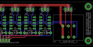
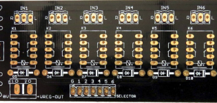
The way to do it is use only half side of the switch. Say left side 1,2,3,4 and their close pin in the center. That pin goes to G, the other pins to 1,2,3,4 on the PCB selector header pads next to G. You populate relays for K1,K2,K3,K4 as well. There is a stop ring at the neck of the switch that you can pull up and reset its pin to hole four. So it will not be turning beyond four clicks anymore.
The way the circuit works is the switch sends DC current only through the coil of one relay at a time and energizes it while the rest remain non engaged. Its used as a manual controller not as a signal switch in other words. The input signal ports are selected and routed by the relays.
The way the circuit works is the switch sends DC current only through the coil of one relay at a time and energizes it while the rest remain non engaged. Its used as a manual controller not as a signal switch in other words. The input signal ports are selected and routed by the relays.
Attachments
The way to do it is use only half side of the switch. Say left side 1,2,3,4 and their close pin in the center. That pin goes to G, the other pins to 1,2,3,4 on the PCB selector header pads next to G. You populate relays for K1,K2,K3,K4 as well. There is a stop ring at the neck of the switch that you can pull up and reset its pin to hole four. So it will not be turning beyond four clicks anymore.
The way the circuit works is the switch sends DC current only through the coil of one relay at a time and energizes it while the rest remain non engaged. Its used as a manual controller not as a signal switch in other words. The input signal ports are selected and routed by the relays.
Ahhhh, thanks for that! Much simpler than I imagined!
Russellc
Initial power up question;
Power Supply board is up and running correctly. Preamp board completely assembled, both it and power supply board mounted in chassis. power supply is wired to preamp board.
There is no other wiring. None to RCA jacks, no signal wiring, volume pot not connected to board, selector switch not connected yet, nothing. Only wires from power supply to preamp board.
Also, neither the preamp board nor the power supply board is grounded to chassis, absolutely no other wiring, except power supply is wired to pre amp board. Electrical plug is temporarily attached through variac as when power supply was tested. no power line fuse yet. I suppose I could go ahead and wire the transformers to fuse and IEC plug to at least give some fusing, and ground the IECs ground plug to chassis?
Is this sufficient for initial power up of preamp board (sans opamp) for testing and setting prior to insertion of opamp, or does more wiring need to be done? i.e. RCA jacks wired for shorting jacks, grounds, fuses etc. I am particularly concerned if some grounding should first be done.
I guess to simplify, what is minimum wiring required for test fire up of preamp board? It would be easier (it seems) to test without all wiring in place, so that if a problem exists on preamp board, a lot of de wiring would't have to be done.
I am inclined to at least ground power supply to chassis through a CL-60 therisister as a minimum. If so, (or some other power supply grounding is recommended) from what point(s) should the ground be taken?
Anxious to fire up and test, and
Thanks in advance,
Russellc
Last edited:
No signal wiring is needed to test the basics i.e. bias & offset. Surely connect the chassis to the mains protective earth and fuse the transformers primary. Connecting any board's zero to chassis is not required right now, you may do it if the offset setting procedure seems too jumpy, thus noise is suspected. Good luck with your first power up.
No signal wiring is needed to test the basics i.e. bias & offset. Surely connect the chassis to the mains protective earth and fuse the transformers primary. Connecting any board's zero to chassis is not required right now, you may do it if the offset setting procedure seems too jumpy, thus noise is suspected. Good luck with your first power up.
Sounds good. I will wire up the transformer primaries, IEC, (wiring ground to chassis) and the inline fuse.
Thanks,
Russellc
- Home
- Source & Line
- Analog Line Level
- Salas DCG3 preamp (line & headphone)