TSG,
Please no, I don't think I can take another port tuning inquiry lol
Using Lpads are my first choice but just resisting the whole thing is fine by me too. I have lots of resistors laying about the shop that I can just shove in there. Lots of them with VERY high wattage capacity.
Please no, I don't think I can take another port tuning inquiry lol
Using Lpads are my first choice but just resisting the whole thing is fine by me too. I have lots of resistors laying about the shop that I can just shove in there. Lots of them with VERY high wattage capacity.
Agreed.Flat on-axis must not relay on partial cancelation - it is wrong, as simple as that.
I'm using a class D amplifier...... what should I set the ohm to? I changed it to 4 and it uhhhh....destoryed the whole frequency response.With the simulation model's 2.83V signal source impedance of 1m Ohm (1 milli Ohm), damping factor of 8,000,
this speaker is for operation with a solid state amplifier.
For a tube amp with damping factors typically ranging from 2 to 10, the results will be different.
Set it to 0.15 ohms. Class D amplifier is solid state, it is not a tube amplifier with 4 ohms output impedance. Besides, only tube amplifiers without global negative feedback have such high output impedance.
Interesting. I see you did a similar thing to sonce where you let the woofer and mid cross wayyyyyy into eachother. Is there a benefit to this rather than using a steeper crossover? I feel like you're hardly using the bandwidth of the mid. Almost seems like just filling a small hole in the middle of the response with it rather than really utilizing itI dug in my archives...
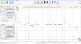
View attachment 1336038
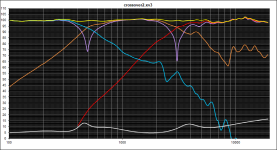
Back in 2012 I finished a 3-way design around the ZA14.
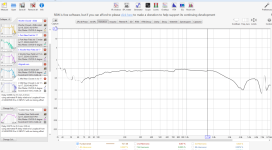
View attachment 1336039
Overall response was pretty okay.
View attachment 1336041
As was the proof of the pudding. Don't pay attention to the part under 200Hz, I didn't mind stitching the LF part for this measurement then.
View attachment 1336042
This in an enclosure of 24cm wide and about 1m high. Just to point out that ZA14 isn't that hard to use and to give some inspiration.
Got it. Will do.Set it to 0.15 ohms. Class D amplifier is solid state, it is not a tube amplifier with 4 ohms output impedance. Besides, only tube amplifiers without global negative feedback have such high output impedance.
I also see you let the mid and woofer cross wayyyy into eachother. Is there a specific benefit to this rather than using a stepper crossover on both of those to increase the bandwith of the mid? Seems like you're hardly utilizing that beautiful mid and a lot of its response is coming from the woofer. The mid's THD is beautifully flat. Both the mid and the woofer have similar THD at the crossed frequencies so I guess it doesn't matter. I just expected the mid to play at a wider spread than both you and Mark show.
Attachments
Well, that is not true in all cases.Having the resistor before the filters is going to give it the entire frequency spectrum and will cause it to have to dissipate a lot more heat. I would definitely put them after the filters and then redesign the filters.
It's good that someone has checked that issue out. The output impedance of solid-state amplifiers is highly unlikely to be a problem.But nothing changed if it is set up to 0.15 ohms (damping factor = 53), which is OK for almost any possible solid state amplifier.
If a loudspeaker is "designed" for use with tube amplifiers, then I would be left wondering which particular tube amplifier was used during the design process. As the damping factors (output impedances) of tube amplifiers are often quite low and can vary widely, there can be significant frequency response differences in a loudspeaker's output depending on which tube amplifier is driving it.Loudspeaker usually are designed for use with solid state amplifier. Only handful are designed for tube amplifiers exclusively.
Yes, benefit is much cheaper crossover (smaller inductors and capacitors). But here you go - lower woofer-mid crossover:I also see you let the mid and woofer cross wayyyy into eachother. Is there a specific benefit to this rather than using a stepper crossover on both of those to increase the bandwith of the mid?
Note the 3.9 mH inductor in the woofer filter changed to 5.6 mH and 47 uF capacitor from the mid filter changed to 120 uF and iductor from 1.2 mH to 1.8 mH.
Important note: you don't have "Y" values - distances between drivers! Crossover above would be correct ONLY IF the drivers are coaxial design! Please post distances between drivers!
Last edited:
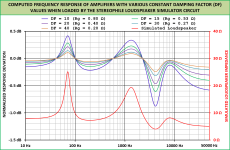
As an example, which may carryover to your amplifier's specifications, the Hypex nCore nc252MP class D amplifier has a damping factor of around 300 referred back to a 4-ohm resistive load. That means that it has an output impedance of 4/300 = 0.013 ohms = 13 milliohms (see the test measurements here:I'm using a class D amplifier...... what should I set the ohm to? I changed it to 4 and it uhhhh....destroyed the whole frequency response.
(https://archimago.blogspot.com/2020/01/measurements-hypex-ncore-nc252mp.html).
The frequency response plots shown below demonstrate the typical effects of output impedance on the frequency response of an amplifier connected to an example loudspeaker impedance load. If it is desired to keep the frequency response variation within ±0.1dB, then in this particular example the amplifier's output impedance needs to be less than or equal to 0.08 ohms.
Solid-state amplifiers usually meet that criteriin without difficulty, so 0.08 ohms could be used as the impedance of the voltage source in your modelling.
Attachments

Now, even lower woofer-mid frequency crossover:


But there is a caveat: impedance between 70 Hz and 250 Hz is becoming dangerously low.
Important note: you don't have "Y" values - distances between drivers! Crossover above would be correct ONLY IF the drivers are coaxial design! Please post distances between drivers!
But there is a caveat: impedance between 70 Hz and 250 Hz is becoming dangerously low.
Important note: you don't have "Y" values - distances between drivers! Crossover above would be correct ONLY IF the drivers are coaxial design! Please post distances between drivers!
Ahh. Higher wattage resistors is a good idea. I thought I saw a 5 watt resistor in line with the mid and that made me a bit nervous. Higher wattage is better. Maybe we should try a passive radiator instead of a port......hahahahTSG,
Please no, I don't think I can take another port tuning inquiry lol
Using Lpads are my first choice but just resisting the whole thing is fine by me too. I have lots of resistors laying about the shop that I can just shove in there. Lots of them with VERY high wattage capacity.
I agree that it's not true in all cases, but I think it's a safer practice, especially for people who are new to crossovers. As I understand it, there's a lot of math with it that's way over my head. It's plenty safe with tweeters but I would be concerned with a resistor first in line with a mid range driver unless the resistor is at least 25 watts (prefer 50). But again, I can't do all of the math. I have, however, had a resistor burn my hand in a mid range circuit when I used it first in line. I've never had that problem when they're after the filters.Well, that is not true in all cases.
Yeah that looks better than what I made. I'll attach the baffle dimensions. I actually tried to change the y axis but it doesn't show up in my driver box. I'll post a snapshot of that too. For some reason it only gives me SPL and Z. I watched a video where someone was changing the y values on the drivers but my screen doesn't look like that.
x, y, and z offset are in crossover section, not the drivers, lower left. See red circle in the attached image.
BUT...you measured all of your drivers on the tweeter's axis, not on thier own axes, correct? In that case, your y-offsets are zero...I think.
Or all measurements were taken on the tweeter axis...I think.Important note: you don't have "Y" values - distances between drivers! Crossover above would be correct ONLY IF the drivers are coaxial design! Please post distances between drivers!
I tend to think that there is no benefit to that greater amount of overlap between the woofer and the midrange. It may be taken to be indicative of the fact that the crossover component values are not as optimal as they could be. In this instance, it's just one possible solution to the crossover design problem that achieves a relatively flat summed response between the woofer and the midrange.I also see you let the mid and woofer cross wayyyy into each other. Is there a specific benefit to this rather than using a steeper crossover on both of those to increase the bandwith of the mid?
That's a very good observation, and I'd tend to try and rework the crossover to have greater output from the midrange unit blending with the woofer. Of course, this may be difficult to achieve.Seems like you're hardly utilizing that beautiful mid and a lot of its response is coming from the woofer.
It does seem to make sense to use the midrange unit over a greater portion of its potential operating range. It would also help to keep any woofer cone breakup resonances more heavily filtered than they might otherwise be.The mid's THD is beautifully flat. Both the mid and the woofer have similar THD at the crossed frequencies so I guess it doesn't matter. I just expected the mid to play at a wider spread than both you and Mark show.
In the design stage, the difficulty lies in controlling the crossover topology as much as possible to get it to perform in the desired way. Simply letting the circuit optimizer produce a valid design, but one that might be sub-optimal from a driver-blending perspective, may result in a loudspeaker that's less good than it could have been.
In this instance, it could prove beneficial to optimize the circuit components of the woofer low-pass filter first, using a desired target function and cut-off frequency. Moving the cut-off frequency around a little bit could be instructive, and result in a good match to the target function. The crossover components on the woofer could then be fixed during optimization of the filtering of the midrange and tweeter.
Yes!x, y, and z offset are in crossover section, not the drivers, lower left. See red circle in the attached image.
Oh no! It didn't occur to me as a possibility! That is wrong - in VituixCAD all driver measurement must be taken at their own axis!BUT...you measured all of your drivers on the tweeter's axis, not on thier own axes, correct?
@Bmsluite ? How did you measure the drivers, on which axis?
Unfortunately, no. That is not how VituixCAD expects to see measured data.In that case, your y-offsets are zero...I think.
Last edited:
If you really want to make some fun, try higher tuning - about 40 - 50 Hz. That can be achieved with shorter port with the same araa, or bigger area port with the same length.In answer to your port question, I will be trying out a lower tuned port just for fun (costs $12 to try, worth it for the fun). I will likely be plugging the port for most music and unplugging it when I want to crank it for some fun
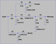
While the measurement offsets issue get sorted out, I thought I'd give it a go anyways even if further tweaking will be required, just to show an alternative topology. As I said before I don't have VituixCAD, I use an Excel spreadsheet I made myself, so I've drawn the schematic in LTSpice, see below.
I know L3 could be tweaked further to catch the midrange peak better but I've tried to use standard / easy to find component values. Note that I only considered the on-axis response and basically aimed at flatness where it matters most, good phase tracking at the crossover points and a reasonable impedance curve. Could be a good starting point for further tweaking. It would be nice if one of you VituixCAD users could kindly enter it there to see what it looks like.
I know L3 could be tweaked further to catch the midrange peak better but I've tried to use standard / easy to find component values. Note that I only considered the on-axis response and basically aimed at flatness where it matters most, good phase tracking at the crossover points and a reasonable impedance curve. Could be a good starting point for further tweaking. It would be nice if one of you VituixCAD users could kindly enter it there to see what it looks like.
Attachments
Well, 330-3k isn’t exactly a small hole, but I think I made a trade-off between directivity and keeping away from the breakup on one side and an easy and not taking ridiculous amount of parts needing low to mid section. I also did not need to, the other drivers excel in the range they cover in this setup. Generally it’s not a bad idea to cross in the 300 to 400Hz region or higher, since one can mitigate floor bounce dips a little bit too.Interesting. I see you did a similar thing to sonce where you let the woofer and mid cross wayyyyyy into eachother. Is there a benefit to this rather than using a steeper crossover? I feel like you're hardly using the bandwidth of the mid. Almost seems like just filling a small hole in the middle of the response with it rather than really utilizing it
On steep slopes: they are easy in active crossovers. Not so in passive ones. If you want steep, go active. This crossover refrained to around 12dB/octave, resulting in fine phase summing, apart from the mid lowpass. That often is more than enough in 3-ways.
Last edited:
- Home
- Loudspeakers
- Multi-Way
- Saggy Bandpass filter