I don't think that is enough room but i will try this.You could rearrange the MCU and inrush unit to get the 6 cm in between the 2 pcb's.
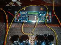
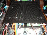
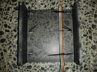
Some photos of the wiring process.
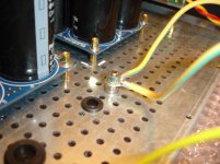
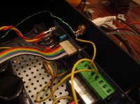
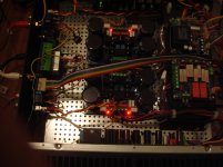
My plan is to wire the 230V A.C underside of the inner base starting as in picture 4(marine and red wire) and ending as in picture 5(marine and red wire),maybe i will add a tube for a better isolation.
Attachments
-
 DSC09134.jpg397.4 KB · Views: 277
 -
 DSC09135.jpg362.5 KB · Views: 270
 -
 DSC09136.jpg399.8 KB · Views: 260
 -
 DSC09144.jpg466.4 KB · Views: 252
 -
 DSC09146.jpg244.2 KB · Views: 248
 -
 DSC09156.jpg250.9 KB · Views: 122
 -
 DSC09147.jpg356.6 KB · Views: 103
 -
 DSC09138.jpg439.7 KB · Views: 105
 -
 DSC09143.jpg591 KB · Views: 106
Last edited:
thimios:
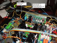
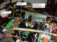
where do you get the parts i point to in red?
and what are their part numbers and names?
mlloyd1
where do you get the parts i point to in red?
and what are their part numbers and names?
mlloyd1
Looks like i have only one remaining position.
This behind the front panel.
... Many cables for arrangement!
Attachments
Modushop by Hi-Fi 2000 | Contenitori per Elettronica | Electronic Enclosures | Hi Fi Chassis
case name: "Dissipante 3U 400mm"
Search for
Ricerca - 1BASEPD400
case name: "Dissipante 3U 400mm"
Search for
Ricerca - 1BASEPD400
Last edited:
...
My plan is to wire the 230V A.C underside of the inner base ...
...
maybe i will add a tube for a better isolation.
Yes you should use an additional isolation level for 230VAC lines. Also keep attention on small signal wires not to be in the near of the inner 230VAC faston sockets.
BR, Toni
Wiring Adventures
Wiring isn't an easy procedure.😡
If the goal is a hum free amplifier the answer is... try and fail.
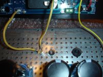
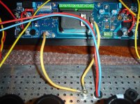
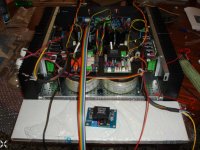
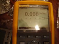
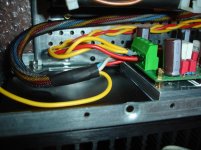
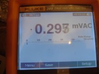
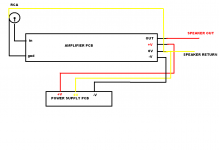
Picture 1, RCA GND on backplane signal GND,noise=297uv(picture 2).
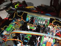
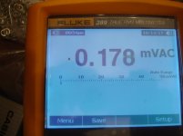
Picture 3, RCA GND+SPEAKER RETURN to amplifier 0V connection,better but still 175uV.(PICTURE 4).
Picture 5, RCA GND+Speaker return to amplifier 0V BUT the wire for RCA GND separated,noise PRACTICALLY.. ZERO.hum FREE!😎
Wiring isn't an easy procedure.😡
If the goal is a hum free amplifier the answer is... try and fail.
Picture 1, RCA GND on backplane signal GND,noise=297uv(picture 2).
Picture 3, RCA GND+SPEAKER RETURN to amplifier 0V connection,better but still 175uV.(PICTURE 4).
Picture 5, RCA GND+Speaker return to amplifier 0V BUT the wire for RCA GND separated,noise PRACTICALLY.. ZERO.hum FREE!😎
Attachments
Last edited:
Yes,i hope this will help.
Attachments
Last edited:
Zero noise looks like a measurement error. (Relay off?) Wideband noise on output with a short circuit input should always be measureable. output 8R load should be connected during measurements.
Wideband noise (0 - 500kHz) in my test setup was something like150 - 170 uV which is hardly reachable in the ready made amplifier.
Wideband noise (0 - 500kHz) in my test setup was something like150 - 170 uV which is hardly reachable in the ready made amplifier.
Last edited:
Missing the connection to backplane silent ground?Yes,i hope this will help.
Yes this silent GND (green connector)connected to power supply 0V only for safety earthing via bridge.Missing the connection to backplane silent ground?
All wires will be trimmed and fixe in the final procedure.
Attachments
Last edited:
All measurements was taken under load many-many times looking at the speaker relay led but for sure i will measure again😉Zero noise looks like a measurement error. (Relay off?) Wideband noise on output with a short circuit input should always be measureable. output 8R load should be connected during measurements.
Wideband noise (0 - 500kHz) in my test setup was something like150 - 170 uV which is hardly reachable in the ready made amplifier.
I have used my ear in close condaction with speaker also.
This 0 mV AC ,SOMETIMES vary between 70uv and 0.
Last edited:
Ah !Yes,i hope this will help.
create the Main Audio Ground (MAG) right next to the amplifier where all the voltage references use the SAME voltage as a reference to set their levels.
I can't measure to the levels you are able to use, so I see 0.0mVac when I measure the output noise using that MAG location. A DMM that reads 0.0mVac is telling us that the signal is <50uVac.
I have been recommending this for years.
Although TomChr uses a different description, I think his recent experiments and amplifier developments have arrived at the same arrangement.
Last edited:
Some very quiet power amplifiers are reported with output noise in the audio band with roughly 20uVac to 50uVac.All measurements was taken under load many-many times looking at the speaker relay led but for sure i will measure again😉
I have used my ear in close condaction with speaker also.
This 0 mV AC ,SOMETIMES vary between 70uv and 0.
D.Self uses -96dBu as his target for low noise and this equates to ~12.3uVac and that is equivalent to Ein~4nV/rootHertz (when amp gain =+26dB).
Last edited:
Yes this silent GND (green connector)connected to power supply 0V only for safety earthing via bridge.
All wires will be trimmed and fixe in the final procedure.
Perfect! Looks like you have found the optimum for your amplifier.
Having in mind AndrewT "a DMM shows 0 if you measure below 50µV noise": SA2015/SA2016 noise measurements have been about
- 38 µV A-w,
- 50µV 20kHz bw
- 96µV 80 kHz bw
- 180 µV full bw (up to 500kHz)
BTW: Gain is about 31.4 or ~ 30 dB
Last edited:
Yes ,i can confirm this,noise measurement is most time zer😵utput to 4R speaker, regardless if input is open or connected.
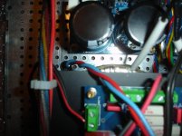
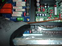
Because the pcb connector can't handle 3 thick wires finaly i have used a piese of pcb.
3 wires(speaker return,RCA GND,0V P.S) solderd on the mini pcb,then one wire connected to 0V amplifier's connector.This placed very closely to amplifier board in a shrink tube.
Because the pcb connector can't handle 3 thick wires finaly i have used a piese of pcb.
3 wires(speaker return,RCA GND,0V P.S) solderd on the mini pcb,then one wire connected to 0V amplifier's connector.This placed very closely to amplifier board in a shrink tube.
Last edited:
All these work well up to the time when a laptop was connectedYes ,i can confirm this,noise measurement is most time zer😵utput to 4R speaker, regardless if input is open or connected.
Because the pcb connector can't handle 3 thick wires finaly i have used a piese of pcb.
3 wires(speaker return,RCA GND,0V P.S) solderd on the mini pcb,then one wire connected to 0V amplifier's connector.This placed very closely to amplifier board in a shrink tube.
Noise ,zzzz. and sometimes like a non tuned radio.Gnd loops!
Tried with an earthed (laptop)power supply.
Noise stop(lower) only when backplane EARTH was pulled.
Then tried a non earthed power supply, better but still noisy.
As a next step was the amplifier was transferred to my house hoping for a more clear not noisy area.
With a non earthed power supply for the laptop, 120mV AC was measured on amplifier output when input was connected to the laptop.It is neccesary to put your ear on the tweeter to be able to hear the noise.
Two laptops was tested.
Finally,amplifier was connected to main speakers and the burn-in period starts!
Last edited:
Finally,amplifier was connected to main speakers and the burn-in period starts!
What do you expect to get burned in?
Best regards!
You mean 120uV or mV?...
With a non earthed power supply for the laptop, 120mV AC was measured on amplifier output when input was connected to the laptop.It is neccesary to put your ear on the tweeter to be able to hear the noise.
Two laptops was tested.
...
BR, Toni
120mV AC output when amplifier input connected to laptop headphone out.😡You mean 120uV or mV?
BR, Toni
News!This measurement is 7mV when mute the laptop out....
Last edited:
- Status
- Not open for further replies.
- Home
- Amplifiers
- Solid State
- SA2015 V-MOSFET Builders