Hi guys
I read briefly through this post (reading it on a cellphone, so it is difficult to see everything), and one thing came to my mind: a lot was said about the B&G Neo3 at the beginning of the post, so has anyone thought of maybe loading both the front and the rear sides directly with two Dayton waveguides (10-inch WGs maybe)? Mounting this structure on a baffle might be tricky, and I am not sure how this loading will affect the Neo3, but then you'd have true DI-pole (as opposed to BI-pole) loading. Any thoughts?
Enjoy,
Deon
The sound is meant to radiate from the same point on the baffle, front and rear wave.
The tweeters are meant to be back to back, aligned in exactly the same point on the baffle at the back and the front
Hi Deon,
Sorry I should have read your post more carefully. I thought you meant two pairs of Dayton waveguides with a pair of the usual compression drivers.
Sorry I should have read your post more carefully. I thought you meant two pairs of Dayton waveguides with a pair of the usual compression drivers.
I would like to understand this better, would it not also be desirable to have the exit of the waveguide at the same position for both drivers for proper dipole operation?
However if this is the case then this is unobtainable with regular baffle mounting surely?
However if this is the case then this is unobtainable with regular baffle mounting surely?
The most important thing is a good phase alignment of the wave-guide and the mid. Dipole follows the same laws with crossover as box.I would like to understand this better, would it not also be desirable to have the exit of the waveguide at the same position for both drivers for proper dipole operation?
However if this is the case then this is unobtainable with regular baffle mounting surely?
The most important thing is a good phase alignment of the wave-guide and the mid. Dipole follows the same laws with crossover as box.
Hi Jerome,
Thanks, I already understand that much, but that doesn't really answer the question.
DX25 + WG300
The Monacor waveguide fits perfectly with DX25.
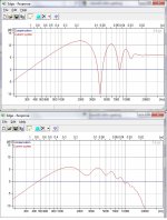
Here is an indoor measurement. I need to get better data later outdoor, but it should not be too far off.
Normalised graph (woofer is Seas W22)

In essence it is able to hold directivity, although not as smooth as compression driver + 10" horn. The main issue only happens at about 10khz, so I think that's high enough.
There is none of that 2khz-5khz bloom with normal dome tweeters.
The waveguide is very shallow and quite small (17cm diameter), so I was able to mount them physically back to back. It sounds good and easy to equalise.
Here is the same data with different view

Compare with NaO note which is the current dipole directivity reference:
Seeing that XT25, Scan Speaks, etc. have the same faceplate as DX25, they could make an interesting combination. Especially XT25 with its phase plug.
The Monacor waveguide fits perfectly with DX25.
Here is an indoor measurement. I need to get better data later outdoor, but it should not be too far off.
Normalised graph (woofer is Seas W22)
In essence it is able to hold directivity, although not as smooth as compression driver + 10" horn. The main issue only happens at about 10khz, so I think that's high enough.
There is none of that 2khz-5khz bloom with normal dome tweeters.
The waveguide is very shallow and quite small (17cm diameter), so I was able to mount them physically back to back. It sounds good and easy to equalise.
Here is the same data with different view
Compare with NaO note which is the current dipole directivity reference:
An externally hosted image should be here but it was not working when we last tested it.
Seeing that XT25, Scan Speaks, etc. have the same faceplate as DX25, they could make an interesting combination. Especially XT25 with its phase plug.
DX25 + WG300
The plots show what appears to be some form of resonant behaviour around 1700 hz, 6000Hz, and 15,000hz?
From BASTA a quick check of a circular baffle with a 25mm source shows diffraction contributions in this range. On axis and 45 degrees off axis plot below. Has the waveguide edge been rounded?
The plots show what appears to be some form of resonant behaviour around 1700 hz, 6000Hz, and 15,000hz?
From BASTA a quick check of a circular baffle with a 25mm source shows diffraction contributions in this range. On axis and 45 degrees off axis plot below. Has the waveguide edge been rounded?
Attachments
Every waveguide has a frequency where it starts to "guide" the wave. Above that frequency the outer rim of the waveguide becomes meaningless - it is no longer "seen" by the wave. EDGE simulations obviously are no longer applicable in that case.
Forget about EDGE at 45°. It does not work there any more.
Forget about EDGE at 45°. It does not work there any more.
The graph is dispersion plot, so it shows off-axis variation.
The loading of dome with the waveguide of course created resonance, which is easily corrected with a notch filter.
I've been very happy with the performance... time to create a proper baffle 🙂

The loading of dome with the waveguide of course created resonance, which is easily corrected with a notch filter.
I've been very happy with the performance... time to create a proper baffle 🙂
I'm thinking of doing a dipole with an AE TD15M and a SEOS-15 waveguide.. this thread has been a big source of contemplation for me.
While I do enjoy the sound of speakers with rear radiation, do you think it would be worthwhile to damp out the rear radiation of the dipole woofer (with 8" of OC703) to match it to the the horn's lack of rear radiation? That way i'll still have the dipole bass effect to the sides of the speaker but without the unbalanced response of rear radiation into the room....????
While I do enjoy the sound of speakers with rear radiation, do you think it would be worthwhile to damp out the rear radiation of the dipole woofer (with 8" of OC703) to match it to the the horn's lack of rear radiation? That way i'll still have the dipole bass effect to the sides of the speaker but without the unbalanced response of rear radiation into the room....????
The only way you get dipole is if you let the rear come out unfettered.I'm thinking of doing a dipole with an AE TD15M and a SEOS-15 waveguide.. this thread has been a big source of contemplation for me.
While I do enjoy the sound of speakers with rear radiation, do you think it would be worthwhile to damp out the rear radiation of the dipole woofer (with 8" of OC703) to match it to the the horn's lack of rear radiation? That way i'll still have the dipole bass effect to the sides of the speaker but without the unbalanced response of rear radiation into the room....????
Sorry, not accustomed to such data and totally misread the plot. This might be interference rather than a resonance, wouldn't a notch filter apply equally at all angles?The graph is dispersion plot, so it shows off-axis variation.
I've been very happy with the performance... time to create a proper baffle 🙂
Do you have a target for the mid driver center to tweeter center distance?
In his 'Development of a compact Dipole' Linkwitz has a plot showing beamwidth and power response of a two dipole array Vs the driver spacing / wavelength ratio in which a value of 0.86 appears critical.
The addition of the two drivers at the crossover is of interest: whilst 24dB/Octave is steep it is not a cliff and the waves will add at frequencies (albeit at reduced level) well away from the nominal crossover point. Perhaps the frequency at which the mid is 10 dB below the tweeter may be a suitable target to start considering the interference? For example with a crossover at 1200 Hz, an LR4 crossover would put the mid driver 10 dB below the tweeter at around 1800 Hz, at which the wavelength is 190 mm and a target center to center distance might be 190 x 0.86 = 165mm. The size and edge shape of the WG300 is an aid in getting the two drivers this close together, though some notching of the guide may be required.
Falstad has an interference java applet that I found interesting:
Sound Wave Interference Applet
As often is the case the numbers in the model don't add up perfectly to what is in the measurements, though guidance to 'minimising' lobing is consistent and calls for a low crossover frequency and low intra-driver distance.
Hi Gainphile,
Do you think this is the best sounding compromise so far?
"almost there" ... as usual 😀
It's great really. I could walk around the speaker and notice both the midrange and tweeter reduced in level. This effect is not there when normal dome is used. Effectively I could move around and the sound do not change !
There is an issue with loading domes with no phase-plug, which is a dip at about 12khz. This is why it would be most interesting to try XT25. Remember that compression drivers all have phase plug to overcome this.
I'm thinking of doing a dipole with an AE TD15M and a SEOS-15 waveguide.. this thread has been a big source of contemplation for me.
While I do enjoy the sound of speakers with rear radiation, do you think it would be worthwhile to damp out the rear radiation of the dipole woofer (with 8" of OC703) to match it to the the horn's lack of rear radiation? That way i'll still have the dipole bass effect to the sides of the speaker but without the unbalanced response of rear radiation into the room....????
I wish it could ! See my front radiation plot using front dayton 10" and D220Ti and DE250 !... but alas it's not bearable long-term. The effect can be investigated/understood this way: Put a switch on rear tweeter (dome or whatever) and run a long cable to listening position. Play with it and the effect is not subtle.
Sorry, not accustomed to such data and totally misread the plot. This might be interference rather than a resonance, wouldn't a notch filter apply equally at all angles?
Do you have a target for the mid driver center to tweeter center distance?
In his 'Development of a compact Dipole' Linkwitz has a plot showing beamwidth and power response of a two dipole array Vs the driver spacing / wavelength ratio in which a value of 0.86 appears critical.
The addition of the two drivers at the crossover is of interest: whilst 24dB/Octave is steep it is not a cliff and the waves will add at frequencies (albeit at reduced level) well away from the nominal crossover point. Perhaps the frequency at which the mid is 10 dB below the tweeter may be a suitable target to start considering the interference? For example with a crossover at 1200 Hz, an LR4 crossover would put the mid driver 10 dB below the tweeter at around 1800 Hz, at which the wavelength is 190 mm and a target center to center distance might be 190 x 0.86 = 165mm. The size and edge shape of the WG300 is an aid in getting the two drivers this close together, though some notching of the guide may be required.
Falstad has an interference java applet that I found interesting:
Sound Wave Interference Applet
As often is the case the numbers in the model don't add up perfectly to what is in the measurements, though guidance to 'minimising' lobing is consistent and calls for a low crossover frequency and low intra-driver distance.
Yes, ideally I wanted to get them as close as possible but I need to make space for the rear horn 🙂. The effect is I have to lower the crossover point... now doing 1200hz and being loaded, the tweeter seems to be fine with it. The woofer definitely loving it, and playing cleaner. At the moment it's 3.5cm between the edges of the drivers, but once this baffle is completed (it's a prototype still) I'll find out if playing around with the location of rear waveguide is worthwile.
I'm really looking forward to the day when all acoustics are sorted and I can buy a nice expensive wood and make them pretty 😀
Yes, ideally I wanted to get them as close as possible but I need to make space for the rear horn 🙂. The effect is I have to lower the crossover point... now doing 1200hz and being loaded, the tweeter seems to be fine with it. The woofer definitely loving it, and playing cleaner. At the moment it's 3.5cm between the edges of the drivers, but once this baffle is completed (it's a prototype still) I'll find out if playing around with the location of rear waveguide is worthwile.
I'm really looking forward to the day when all acoustics are sorted and I can buy a nice expensive wood and make them pretty
Looks like we are on the same wavelength 😎
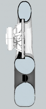
For next step of getting the WG to line up with the mid driver I ended up with a section like in this pic.
The mid baffle has a cross section of an ellipse which twists as it goes around the driver, creating a moebius shape and filling the gap to the tweeter, and paying some homeage to the goal of a non constant dipole D. In this version I settled for driver spacing of 180mm.
The tweeter is to be similar though is a work in progress and I have made about 50 drawings trying to get it to look right, still not there hence why it is all still on paper. Prompted by this discussion I will see how it looks with the WG made oval in front view to close the intra driver distance.
I would have preferred the two drivers to be physically equal distant to the listening position rather than rely on a tweeter delay in the crossover, I was concerned that a signal delay to the tweeter might fix the front waves sum, though double the error at the rear? I might just tilt the whole panel, with all that that carries to the polar pattern.
The only acoustic issue would appear to be in the rear radiation which shows the same structure based low pass filter effect seen in larger drivers, only at a higher frequency. In my case I think its around 8Khz and dont see value in working on it by increasing the opening in the rear.
This is the part where I stall until next Winter. Moving to Geelong this month and the other half has remarked of how 'the best wood carvers have the ugliest wives'.
Attachments
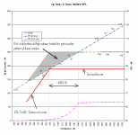
A point on crossover frequency selection and polar pattern trades
Getting the 'right' crossover frequency caused me some angst and led to using the WG300 so it might be worth passing on. Personal opinions on targets of volume Vs roughness will vary widely so this approach may not appeal to all.
The X max sets a distortion limit that can be found subjectively. I haven't tried this yet but it might also be possible to map the roughness more accurately objectively using the SRA (see SRA 2.0 © 2008 - Spectral and Roughness Analysis of Sound Signals ).
There is also a limit to when it is just too loud and I want to turn it down, which for me in a small room this seems to be quite a low volume.
By mapping the distortion 'edge' and volume limit a trade can be made between sound quality at low volume ( polar response ) and sound quality at high volume ( X Max limited distortion).
This can guide to a crossover point hundreds of Hz lower than picking the knee point from a line on the suppliers graphs and lead to a substantial change in the target for inter driver distance for interference.
For me the WG was all about getting the amplification to maximise the driver efficiency and minimise the extent of this X Max distortion trade, hence a WG at both front and rear.
Attachments
- Status
- Not open for further replies.
- Home
- Loudspeakers
- Multi-Way
- S16 - Constant Directivity Dipoles