Harsch makes me want to listen to the music, letting me forget to adjust things forever. Harsch is in my experience less "in your face", and may be a tad less detailed than LR12. For the lack of better words, it reminds me a little bit about a analog glow in the music, that I have yet to experience with LR12.
I have a theory that with a slanted baffle, Harsch may disperse less sound to the ceiling, hence the sound from this 1st reflection is less prominent.
Can someone point to a diagram showing the lobe of Harsch-filter. May have been posted in this thread?
You could also try an MTM with LR4 - seems to work just fine - also with vertical dispersion control:
Heissmann Acoustics | DXT-Wave | d appolito tower speaker
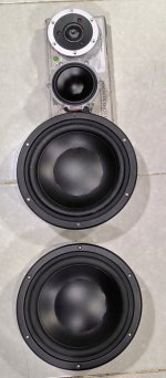
decided to build separate box for my audio nirvana instead of 2 fullrange on my OB. covered previous 12" hole and i think it's a little weird looking between 21" to 5" but sound wise no issue at all
maybe my harsch xo journey finished here, start on another build
maybe my harsch xo journey finished here, start on another build
Attachments


You could also try an MTM with LR4 - seems to work just fine - also with vertical dispersion control:
Heissmann Acoustics | DXT-Wave | d appolito tower speaker
Not into MTM 🙂 They seem to measure fine, but that SEAS tweeter has nasty Odd order harmonics down in the audioband because of the membrane.
here is my latest 3 way OB work in progress.
i first tried Harsch as proposed by xrk:
BW4 - bessel2 - bessel2 - BW4
XO points 200 and 700hz, delay 2.5 and 3.7
sounded good, but then i thought because of the small top baffle i have rolling off tweeter response at XO.
so i tried
BW4 - bessel2 - BW4 - bessel2
slightly better.
then i decided to compare it to a similar all LR set up.
to make it apples to apples i chose
LR4 - LR2 - LR4 - L2
and also applied the same delays as in Harsch.
Both config. are better in imaging/soundstage compared to my prior efforts. Between the two I prefer the comparable LR config. Harsch is sharper and rougher around the edges and also more forward. LR is more natural and musical.
LR4/2 with delay is also much better in imaging compared to without delay: better separation and vocals have an amazing immediacy.... very very good indeed. I am sticking with this for now. I am hoping to start measuring soon.
Attachments

Last edited:
This thread inspired me. I converted my 3 way stand mounts to Harsch crossovers. I followed the BW4 LP, BS2 HP - BS2 LP, BW4 HP with the delays and the 1.27 offset between the crossover points. I have not done measurements yet but I think I'm liking the results. I hate to use subjective terms about audio but listening to the results has me thinking like a TAS reviewer. It may be the power of suggestion but the change to the sound of percussions was the first thing I noticed, they are just crisper if that is the right turn. I just have random music playing all day and a Bob Dylan song came on and the acoustic guitar just sounded better, more real, not sure again, but it was better. Mozart symphonies also stood out. Hopefully when I measure it will look good and not be a hot mess proving that I have a bad ear. Thanks to all of you for doing all the hard work for me. 😀
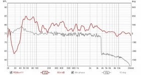
Here is a measurement I made, it is at 1m on axis at tweeter level in my office which is 8' x 10' and very cluttered so I smoothed it to 1/6. The one thing is the minimum phase plot jumps 360 degrees at 3.8khz , is this from a delay if so I would assume it would be at the mid low pass at 450 hz. I use a USB mike, maybe that makes the phase measurements useless.
Attachments
Lots of neat work here guys. Thanks for sharing.
Zmyrna,
For some speakers, LR2 or LR4 may integrate better. Especially with planar tweeters. Did you simply do DSP filters to achieve the BW4 and Bes2 function electronically or are the BW4 and Bes2 filters get developed to be the overall electro-acoustic (measured) filters? It needs to be the latter to be effective. You have to combine the electrical filters with the native response of the driver to arrive at the textbook measured Harsch shapes. You may not be listening to a true Harsch if you simply apply the electronic functions.
Mtidge,
Your jump might be just the plot - click on the settings “gear” icon and click “unwrap phase”.
The phase should have a 55deg rise to the left of the XO if you did it textbook perfect Harsch. Only way to do that is to measure the raw and apply parametric until the electro-acoustic filter matches the textbook shape.
If it sounds more coherent on timing of percussion it is doing it’s job.
Last edited:
Applying these configurations without simulation and measurements is a bit working in the dark. I would advise to start with putting the configuration in Vituixcad and validate how it works there. For me, only BW4 with BS2 on top worked, but not in reverse order...
What crossover freq do you have mtidge?
What crossover freq do you have mtidge?
Woofer has a LP BW4 at 454hz. Mid consists of HP BS2 at 561hz and a LP BW4 at 4237hz. Tweeter has a HP BW4 at 4489hz. The odd numbers are because I'm using a QSC Basis 922az DSP and it has fixed frequency steps. I will try modeling, but moving the speaker, amp and dsp is a pain and my office is not a good room for measurements.
1. Set the low pass filter for the woofer as a 4th order Butterworth at central frequency, fc for the XO centerpoint.
2. Set the high pass filter for the tweeter as a 2nd order Bessel at fc.
3. Set the delay of the tweeter equal to 1/2 of the period of one cycle at fc.
4. Use all positive phase on woofer and tweeter.
Excuse my ignorance please. Can someone please explain to me what central frequency and fc is?
Understood, thank you!fc is the central frequency or crossover frequency. When someone says the crossover is at 2Hz, the fc of the crossover is 2kHz.
You seem to use Harsch inspired crossovers for most of your passive speakers. Do you achieve the delay through physical offset of the drivers?fc is the central frequency or crossover frequency. When someone says the crossover is at 2Hz, the fc of the crossover is 2kHz.
I think I’m the only one who has implemented Harsch XO passively. It’s mostly through use of a higher crossover frequency so that the delay is matched to the natural delay of the driver/filter combo. Sometimes, use of a waveguide is needed to bring the tweeter location farther back. It always requires a woofer that is well behaved and with higher upper end extension. It’s also advantageous to put the second order electrical filter frequency to coincide with the woofer natural falloff for an electrically simple 4th order filter.
Wow! That's pretty involved. Makes sense why it's mostly uncharted territoryI think I’m the only one who has implemented Harsch XO passively. It’s mostly through use of a higher crossover frequency so that the delay is matched to the natural delay of the driver/filter combo. Sometimes, use of a waveguide is needed to bring the tweeter location farther back. It always requires a woofer that is well behaved and with higher upper end extension. It’s also advantageous to put the second order electrical filter frequency to coincide with the woofer natural falloff for an electrically simple 4th order filter.
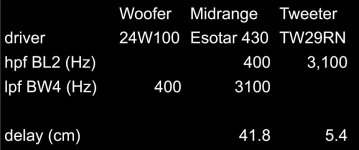
So I got to thinking if this can be applied to a 3-way by mirroring the XO topology. That is Butterworth 4th order for the low pass on the woofer, Bessel 2nd order for the mid high pass and Bessel 2nd order for the mid low pass (or Bessel 2nd order bandpass for mid), and a Butterworth 4th order for the tweeter high pass.
I am confused. Between the tweeter and the mid, the tweeter has the 4th order Butterworth crossover and the mid has the 2nd order Bessel crossover, so the tweeter gets the delay.The tricky thing is what to do for the time delays? Well, it is exactly the same delay assuming driver acoustic centers are already time aligned. The mid needs to be delayed from the woofer by 0.5/fc_low and the tweeter needs to be delayed from the mid by 0.5/fc_high. For my case, I used a 500Hz and 3500Hz XO points:
Then, the mid gets the 2nd order and the woofer gets the fourth order but the mid gets the delay? Why is this? How is it determined which driver gets the delay?
Based on simulations, I concluded that three way is possible but only with crossovers stacked in same way as two way. So 4th order for woofer and 2nd order for lower crossover of mid. And then 4th order for mid towards 2nd order of tweeter. Delay as in two way for mid, same for tweeter but also add mid delay. If crossover frequencies are close by, you get a bit less flat frequency spectrum. But you can this tweak partly away...
Have fun!
Have fun!
I am confused. Between the tweeter and the mid, the tweeter has the 4th order Butterworth crossover and the mid has the 2nd order Bessel crossover, so the tweeter gets the delay.
Then, the mid gets the 2nd order and the woofer gets the fourth order but the mid gets the delay? Why is this? How is it determined which driver gets the delay?
This high frequency (high pass filter) always gets the delay.
In DSP world, the low pass could get a negative delay (time advancement) but this only works for non real time systems as you violate cause and effect.
The reason comes down to the theory of this crossover topology - if you want to follow the math as explained by S Harsch.
Heya @xrk971 or whoever might know...
The Harsch XO seems pretty neato, and I might have an application for it. I built up a little blank study of it in XSIM, and I used online calcs to do 4th order Butterworth / 2nd order Bessel (blank driver is flat FR / flat impedance), I put the delay on the tweeter. FR curve looks right. But phase doesn't look flat, it starts to wrap above the XO frequency (2k in my test scenario).
Am I doin it wrong?
Right click on the amplifier source and adjust total phase until it doesn’t wrap. This is just phase wrap from time of flight difference between microphone and amp for both woofer and tweeter. Minimum phase adjustment basically. Your sim looks correct because the tell tale sign is the dip below the crossover and then rise. Once minimum phase is achieved in the sim you should see a 55 deg bump in phase.
Great to see you achieved this on a passive crossover. But once you put in real FRD’s it might not look so perfect and will require a few more components to address baffle step loss and possibly some notch filters to deal with non flat driver behavior.
I often achieve Harsch passively with minimal components by superimposing natural woofer falloff (nominally 3.5k or 5k on woofers) with 2nd order electrical to get a free 4th order electro-acoustic.
- Home
- Loudspeakers
- Multi-Way
- S. Harsch XO