Hi xrk971
Thanks for you feedback. The dips are 1 or 2 dB - they are higher than in the Harsch paper. I'll need to figure out how to show the plots in the way you are suggesting - since these are post-EQ, I'll have to remeasure them, or find a way of exporting them from the REW filter optimiser. Or possibly use the ACD spreadsheets.
Some older measured responses 1m above floor, 1m from driver, prior to driver EQ:
mid bass

tweeter

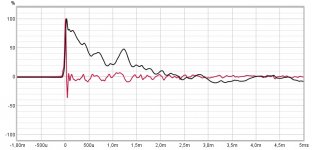
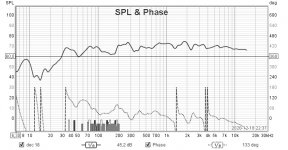
I had dug out an old 50cm measurements - 1m from floor for the LR4 speaker after individual driver EQ, but without BSC.
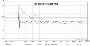
Note the dB impulse response still shows significant floor bounce at 4.4ms.

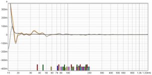
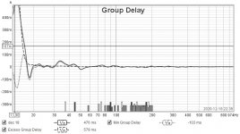
When windowed with 4.4ms Blackman-Nutall window and 10 cycle frequency-dependent window.

And the suggested 6 cycle freq-dependent window:

Curious as to the justification for the 6-cycle window.
Thanks for you feedback. The dips are 1 or 2 dB - they are higher than in the Harsch paper. I'll need to figure out how to show the plots in the way you are suggesting - since these are post-EQ, I'll have to remeasure them, or find a way of exporting them from the REW filter optimiser. Or possibly use the ACD spreadsheets.
Some older measured responses 1m above floor, 1m from driver, prior to driver EQ:
mid bass
tweeter
I had dug out an old 50cm measurements - 1m from floor for the LR4 speaker after individual driver EQ, but without BSC.
Note the dB impulse response still shows significant floor bounce at 4.4ms.
When windowed with 4.4ms Blackman-Nutall window and 10 cycle frequency-dependent window.
And the suggested 6 cycle freq-dependent window:
Curious as to the justification for the 6-cycle window.
Am I doing the math wrong? A 1.5 ms delay means an acoustic offset, on-axis, of (0.0015 sec) * (343 m / sec) = 0.514 m. Does that means it's practically impossible to achieve the necessary delay by physically offsetting the drivers?
Yes, that is why a Harsch XO is not practical for a passive XO unless the frequency is much higher. With DSP, a 1.5ms delay is trivial.
I got this from private communications with Wesayso and Byrtt, the masters of in-room measurements, REW, and FIR DSP processing. It might be suggested somewher in this massive thread:
https://www.diyaudio.com/forums/ful...-driver-range-line-array-223.html#post4709049
here, Wesayso actually suggests 5 cycles. I think the reason is that within 5 cycles of the sound waves of interest (above some cutoff frequency), the sound is gated so that it represents that part that hasn't interacted with the room yet.
Curious as to the justification for the 6-cycle window.
I got this from private communications with Wesayso and Byrtt, the masters of in-room measurements, REW, and FIR DSP processing. It might be suggested somewher in this massive thread:
https://www.diyaudio.com/forums/ful...-driver-range-line-array-223.html#post4709049
here, Wesayso actually suggests 5 cycles. I think the reason is that within 5 cycles of the sound waves of interest (above some cutoff frequency), the sound is gated so that it represents that part that hasn't interacted with the room yet.
Last edited:
Thanks - gosh that is a long thread.
I noticed this in another thread:
Speakers white paper | Grimm Audio
The designer is discussing using LR4, with phase correction.
In section 2.4 he points out:
"The sum of an ideal LR4 system is a second order all-pass with a Q of 0.7. In order to avoid the problems associated with correcting phase exactly, build an inverse all-pass filter based on the theoretical ideal. This filter will be non-causal so there’s a good reason for using FIR."
This is quite appealing - it implies we can have our cake and eat it - get the better above- and below-axis response from LR4, but with perfect phase response on-axis.
He points out the non-causality, as if it is a minor fly in the ointment. I assume his FIR comment means he solves this by delaying the entire signal through an FIR filter, thus allowing a negative delay relative to the output. In other words he is approximating the phase correction (+delay) with an FIR filter.
Here is a related paper:
AES E-Library >> Correction of Crossover Phase Distortion Using Reversed Time All-Pass IIR Filter
That’s why the link I gave is actually the part of the thread that discusses it. Not just page 1.
In that same thread a lot FIR work is used by Wesayso to make his speakers sound perfect. I have heard them before and they are one of the best sounding speakers I have heard anywhere at any price. Amazing sounding. The FIR convoluting and room treatments are key.
In that same thread a lot FIR work is used by Wesayso to make his speakers sound perfect. I have heard them before and they are one of the best sounding speakers I have heard anywhere at any price. Amazing sounding. The FIR convoluting and room treatments are key.
The 5/6 cycle window in REW is a reasonable approximation of the window lengths wesayso uses in his filters so viewing the measurement through it after correction gives you a good idea if it worked.
There is no special significance to it, change the length to see more or less of the room in the measurement. It is better for overall in room responses to gating at a specific point because that will always affect the lower frequencies in a negative way.
There is a pdf here that seems to describe a use of the reversed IIR filter approach that doesn't require AES membership.
http://www.sga-ssa.ch/docs/events/081030_herbsttagung_sga_2008_05adam.pdf
It is still a look forward system but the latency can be less than what you might need for an FIR.
The block diagram could probably be replicated in sigma studio but I'm not aware of anything off the shelf that does it.
Rephase has a filters linearization option where you can generate the inverse phase shift for LR filters. If you really want the phase shift gone and can live with some latency this is an easy way to do it for an existing crossover.
Attachments

Hi all, I've kept harsch xo in the dsp for some time now and it is better than the older presets I've got, which could be for number of reasons 🙂 But, there might be major benefit for domestic listening with the ability to steer some critical mids in vertical plane with tuning of the delay!
At least on my case (a 3-way) it's easily seen on a simulator and is located in a very sensitive region around 1-3kHz where the crossover happens to be. I've attached a gif which is showing what happens when the tweeter delay is increased. I've had the delay so that the "null" is roughly towards where the ceiling bounce would happen, or it might be just how the room sounds when a beam is steered and it is power steering isn't it? I think it could contribute the slight edge over my other dsp snapshots 🙂 Anyone got some view on this?
At least on my case (a 3-way) it's easily seen on a simulator and is located in a very sensitive region around 1-3kHz where the crossover happens to be. I've attached a gif which is showing what happens when the tweeter delay is increased. I've had the delay so that the "null" is roughly towards where the ceiling bounce would happen, or it might be just how the room sounds when a beam is steered and it is power steering isn't it? I think it could contribute the slight edge over my other dsp snapshots 🙂 Anyone got some view on this?
Attachments
Last edited:
Neat idea to steer the vertical sweet spot with digital delay. I suppose similarly it could be done passively with fullrange on moveable mini enclosure.
Indeed, many of us do this (passively or otherwise). I can't speak for the result of doing it randomly. It may not stay within the principles of the Harsch crossover.
This is xrk971 Tl with Purifi and Waveguide with Dayton RST28F with fullrange
Purifi and Bessel at 4458Khz, as BYRRT recomendation and it seems right 🙂
Hopeless room and not the man cave I want but have to accept that...
No delay at tweeter don't manage to get it to work don't sounds good.
I maybe don't know how to calculate it right?
Anyway my son was amazed.
-You never had better sound!I was surronded with it!
🙂
But, maybe there is something to do to get it even better?
I run computer-USB-Komplete Audio 6-slave out SPDIF-nanoDigi-two Khadas DAC.
Yes som EQ is it but nanoDigi don't have so many...
ADAU1466 could do much better but miniDSP plugin is just trivial.
Attachments
I run 3e TPA 3251 four channel at top, only two channel.
3e TPA3255 two channel to Purifi.
OPA1656 in all.
Yes it's better than NE5532. 🙂
Hands down.
But I think I need better to wave guide, just a feeling.
3e TPA3255 two channel to Purifi.
OPA1656 in all.
Yes it's better than NE5532. 🙂
Hands down.
But I think I need better to wave guide, just a feeling.
Last edited:
Very nice work, Solve! That looks great. Glad you got the Harsch sorted out. OPA1656 is a superb opamp.
If you don’t mind, please mention your progress in the Purifi TL thread.
Congrats!

If you don’t mind, please mention your progress in the Purifi TL thread.
Congrats!
Last edited:
In the meantime, I am busy optimizing a Harsch XO for the latest version of my open baffle speaker:

It contains a new custom 15" woofer, 18 sounds 6ND430 mid and Heil AMT tweeter. I put them closer together vertically, compared to the previous speaker I made. I use Mundorf 4.7 ohm series resistor and 60 uF in series with the tweeter to reduce level and protect it (resulting in a first order 312 Hz HPF).
This time, I selected XO points at 300 Hz and 1600 Hz, a bit further apart to avoid mix-up. According Harsch guidelines, the delays should be 312.5 us for mid to tweeter and 1666.7 us for woofer to mid. I simulated this in VituixCAD.

However it looks like a smaller woofer/mid delay (245 us less) improves things a bit:

Earlier in this thread I also read about Harsch variants based on 3rd order BW. This may have benefits. Anyone still using this?
It contains a new custom 15" woofer, 18 sounds 6ND430 mid and Heil AMT tweeter. I put them closer together vertically, compared to the previous speaker I made. I use Mundorf 4.7 ohm series resistor and 60 uF in series with the tweeter to reduce level and protect it (resulting in a first order 312 Hz HPF).
This time, I selected XO points at 300 Hz and 1600 Hz, a bit further apart to avoid mix-up. According Harsch guidelines, the delays should be 312.5 us for mid to tweeter and 1666.7 us for woofer to mid. I simulated this in VituixCAD.
However it looks like a smaller woofer/mid delay (245 us less) improves things a bit:
Earlier in this thread I also read about Harsch variants based on 3rd order BW. This may have benefits. Anyone still using this?
Last edited:
Hi fedde, you should make measurements of the speaker. Ideal drivers won't get you any meaningful results in the simulator. Real measured frequency and phase lets you really tune in the crossover. That said Harsh xo as basis (and tweaked from there) I've achieved the best results yet, better sound than other crossover variations I've tried on my first prototype speaker. I cannot say what atribute is responsible for better sound, need to verify the results somehow. Extensive measurements (spinorama) has helped a lot. The measurements will show what are the natural crossover points, what electrical filters are needed to get the acoustical slopes, diffraction etc. Much better results are quaranteed with measured data, otherwise it is just shooting from the hip. Have fun!🙂
Last edited:
Sure, the simulation is just the theoretical foundation for setting up the filters. By the way, I found it is very easy to create the target curves with VituixCAD. You can select each one of the drivers and do an export of "Frequency response of Driver". The exported text files can directly be dragged into REW, nice:

This turned out to be very handy for debugging where gaps in system response come from (holes in individual curves vs fase issues)... 😎
This turned out to be very handy for debugging where gaps in system response come from (holes in individual curves vs fase issues)... 😎
Interesting project Fedde. Look forward to hearing about how it goes. That 18 Sound mid looks a lot like a Purifi woofer with the dish shaped cone and rippled surround.
The simulation certainly looks like a good way to get initial filters setup. But I have found that combining the natural response of a driver and a lower order electrical filter to get the overall higher order one the best way to go.
The simulation certainly looks like a good way to get initial filters setup. But I have found that combining the natural response of a driver and a lower order electrical filter to get the overall higher order one the best way to go.
Yes, I chose the 18 sounds cause I heard good feedback about it and because of its interesting combination of specs (low distortion, good efficiency, size, Max power, freq response etc) and quite reasonable cost. See:
EIGHTEEN SOUND 6ND430-8 (Mid-woofer 6", 8 Ohm, 500 Wmax)
Distortion is maybe not as low as Purifi but its efficiency is better. And it looks better I think.
Honestly, measuring my speaker and getting Harsch XO dailed in is a huge challenge. Nearfield I can measure driver response quite well, but I do not see the baffle fall off. On 0.5m distance, reflections start to become an issue but probably still not all baffle related influence is in. To measure high frequencies properly I need to be at AMT height, so mid and woofer are further away changing phase and reducing its level. At 1m distance, room influence is even stronger. I also tried to measure bass from the floor which gives somewhat different results. I tried measurement windows and fdw cycles 5, 6 or lower for bass. Matching phase is even harder. I determined phase with LR4 but this did not really translate to Harsch XO. Still I am making progress and will get there over time. With less than perfect freq. response and phase alignment, the sound is still already great IMHO, and better than with LR4.
I already considered following acoustical curves and extending this to the required BW4 curves. The target curve way of working enables this. Probably I would need to raise the lower crossover as falloff starts at 400 Hz from my memory. Probably the woofer could still handle that crossover well.
Last edited:
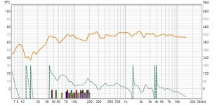
I just made some unfiltered driver measurements in the current baffle design at 1m:

(red = custom 15" woofer, green = 6ND430 mid, blue = ESS AMT)
The AMT has roughly 7 dB reduced level and 1st order HPF at 312 Hz. It starts to lose level at 3 kHz, but stays more or less flat from 700-2000 Hz.
If you look to the mid driver response, a 3rd or 4rd order HPF curve at 500 Hz fits... 😕
Perhaps I have to add short wings to lower this point?

- Home
- Loudspeakers
- Multi-Way
- S. Harsch XO